Direct cooling system and method for transceivers

a technology of direct cooling and transceiver, which is applied in the direction of electrical apparatus casing/cabinet/drawer, coupling device connection, instruments, etc., can solve the problems of inefficiency of external heat sink, inability to focus cooling of internal components of transceiver modules, and design challenges of conventional external heat sinks

Active Publication Date: 2012-07-19
AVAGO TECH INT SALES PTE LTD
View PDF34 Cites 32 Cited by
  • Summary
  • Abstract
  • Description
  • Claims
  • Application Information

AI Technical Summary

Problems solved by technology

Optical communications systems present a number of implementation challenges.
However, such external heat sinks are inefficient as they cool all internal components of the transceiver module 10 to roughly the same temperature.
Such external heat sinks do not allow for focused cooling of the internal components of the transceiver module 10 with lower operating temperatures, while not cooling internal components having maximum allowed operating temperatures.
Additionally, conventional external heat sinks provide design challenges in instances in which many transceiver modules are arranged closely together in connected cages.
One such design challenge is that a conventional heat sink mounted to the top surface of the cage 34 prevents stacking transceiver modules on top of each other because only the uppermost transceiver module 10 is in contact with cage 34 and thus only the uppermost transceiver module 10 receives adequate heat dissipation.

Method used


Image

  • Direct cooling system and method for transceivers
  • Direct cooling system and method for transceivers
  • Direct cooling system and method for transceivers

Examples


Embodiment Construction

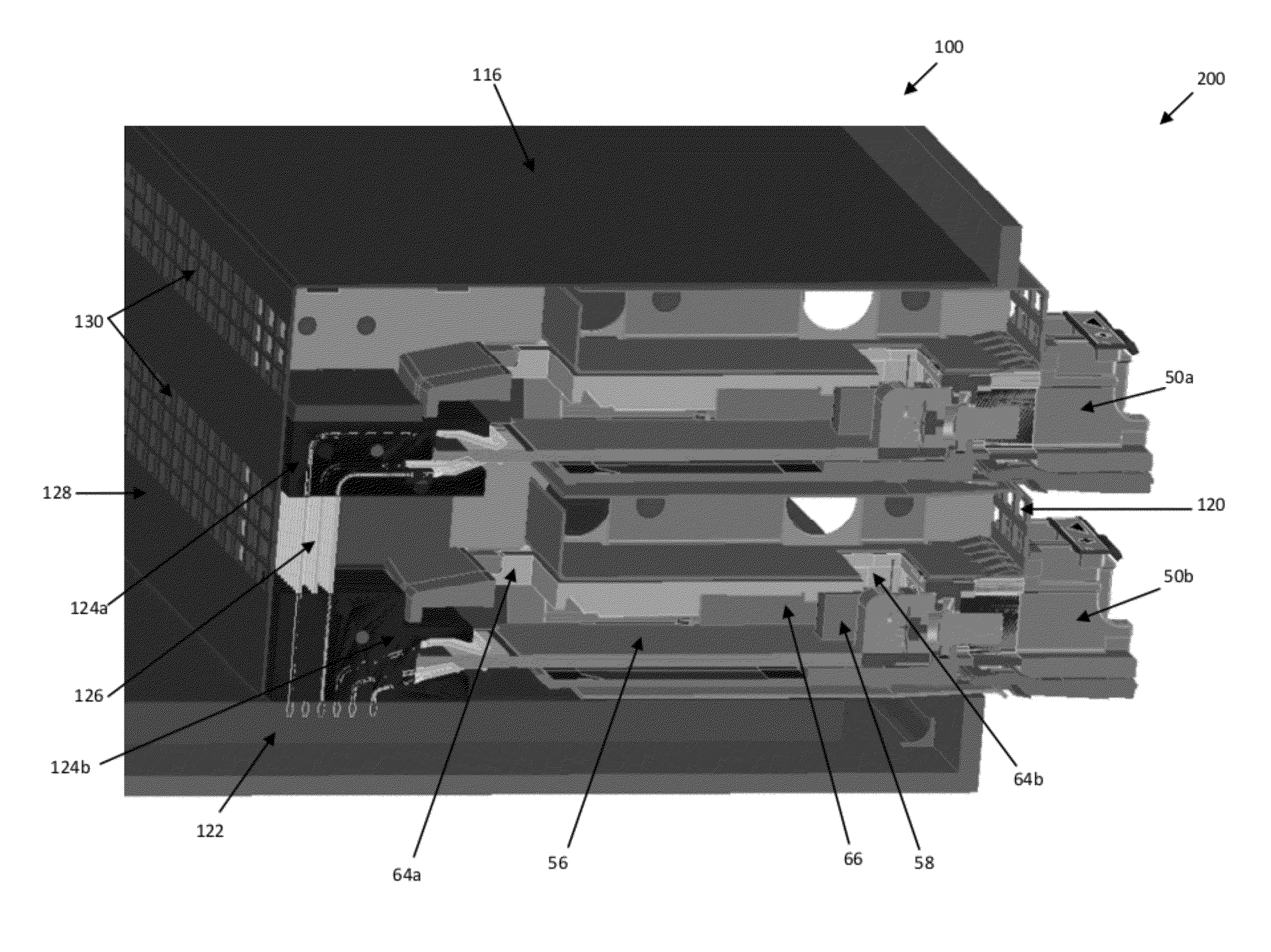
[0022]Referring initially to FIG. 3, an illustrative or exemplary embodiment of the invention which includes optical transceiver module 50 is shown with an elongated, generally rectangular shape defined by an elongated housing assembly 52 with a receptacle 54 disposed at a front end of housing assembly 52. Depending on the type of receptacle 54 used, the receptacle 54 can accept a single-fiber (or “simplex”) optical cable plug connector or dual-fiber (or “duplex”) optical cable plug of the various types known for use with electrical or optical systems.

[0023]Although in the exemplary embodiment the housing assembly 52 is shown as one unit (with part of the housing assembly 52 cut away in FIG. 3 for ease of understanding the optical transceiver module 50), the housing assembly 52 may be comprised of separate pieces that are connected together to form the housing for the optical transceiver module 50 (see FIG. 4). Unless specifically stated otherwise, any element described herein or a ...


PUM


Abstract

Systems and methods for direct cooling of transceivers, including transceivers used in electrical and optical communications systems. An electrical system includes a transceiver module with a housing that contains a plurality of apertures to allow air flow into and out of the transceiver module. The transceiver includes an internal heat sink located within the housing of the transceiver module, where the internal heat sink is thermally coupled to at least one internal component of the transceiver module. The electrical system also includes a cage for receiving and electrically connecting to the transceiver module. The cage contains a second set of apertures such that when the transceiver module is inserted into the cage, air may flow into the cage through the second set of apertures, then flow into the transceiver module through one of the plurality of apertures in the transceiver module housing such that the air dissipates heat from the at least one internal component thermally coupled to the internal heat sink. The air may then flow out of the transceiver module through another of the plurality of apertures in the housing.

Description

TECHNICAL FIELD OF THE INVENTION[0001]This invention relates generally to the field of transceivers. Exemplary embodiments relate to systems and methods for direct cooling of transceivers, including transceivers used in electrical and optical communications systems.BACKGROUND OF THE INVENTION[0002]Fiber optics are widely used as a medium for transmitting voice and data signals. As a transmission medium, light provides advantages over traditional electrical communication techniques. For example, light signals allow for relatively high transmission rates as well as for transmission over great distances without signal loss, and light signals are resistant to electromagnetic interferences that can interfere with electrical signals.[0003]Optical communications systems present a number of implementation challenges. For example, the data carried by light signal must be converted from an electrical signal to light at the sending device, and then converted from light back to an electrical si...

Claims


Application Information

Patent Timeline
Patent Type & Authority Applications(United States)
IPC IPC(8): H05K7/20
CPCG02B6/4269H04B10/40
Inventor MCCOLLOCH, LAURENCE RAYYU, PAUL
Owner AVAGO TECH INT SALES PTE LTD
Why Eureka
Try Eureka