Architecture for a 3D memory array

a memory array and architecture technology, applied in the field of high density memory devices, can solve the problems of memory cell endurance problems and other complexities, and achieve the effect of minimizing capacitance differences among global bit lines

Active Publication Date: 2012-07-19
MACRONIX INT CO LTD
View PDF4 Cites 69 Cited by
  • Summary
  • Abstract
  • Description
  • Claims
  • Application Information

AI Technical Summary

Benefits of technology

[0013]Techniques are also described herein for connecting access lines, including global bit lines, to a variety of lev

Problems solved by technology

These variations can lead to endurance problems with the memory cells and to other complexities.
These variations in capacitance affect the global bit line voltages during read, program and er

Method used


Image

  • Architecture for a 3D memory array
  • Architecture for a 3D memory array
  • Architecture for a 3D memory array

Examples


Embodiment Construction

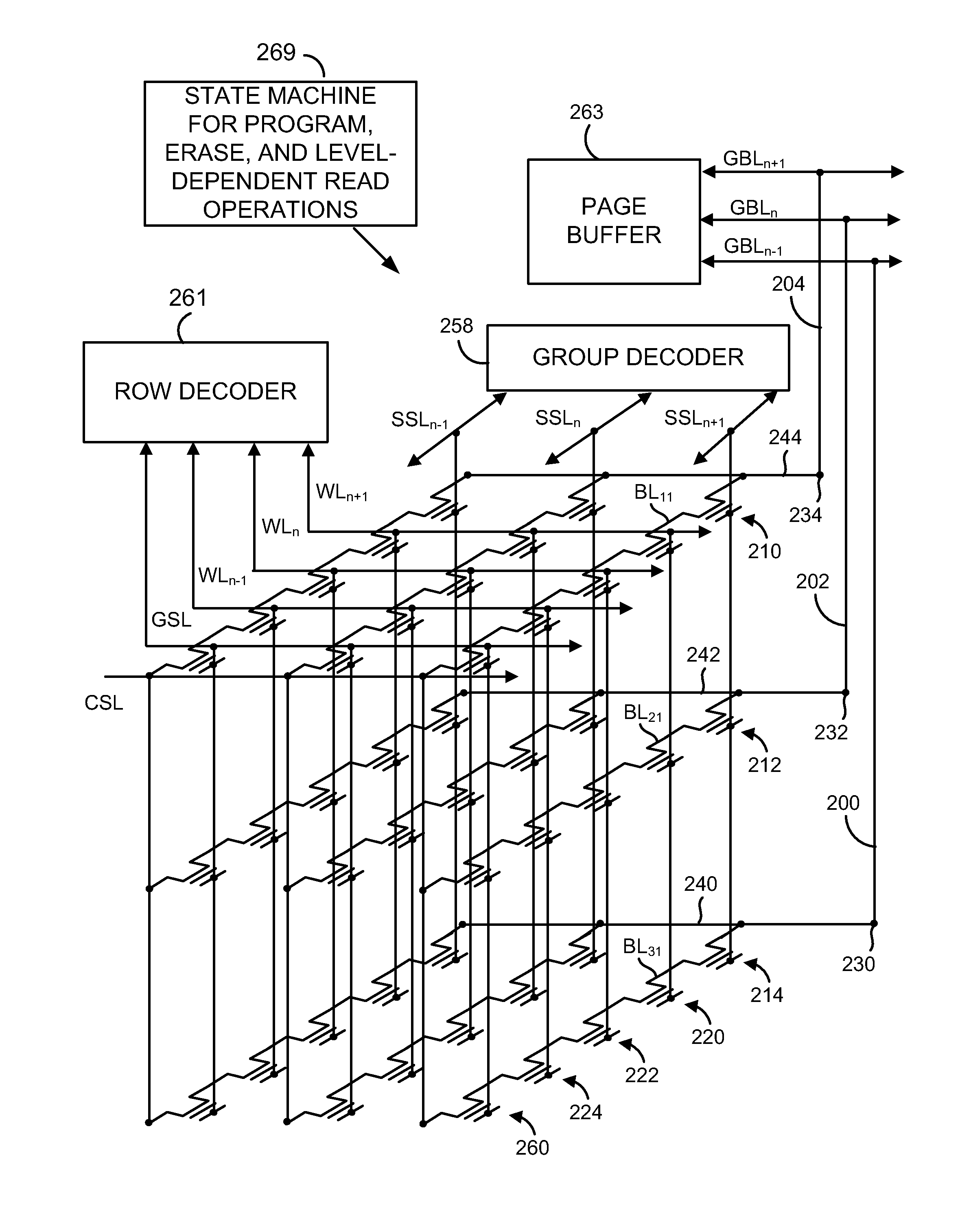
[0028]Techniques are described herein for compensating for threshold voltage variations among memory cells in an array by applying different bias conditions to selected bit lines.

[0029]The compensation technology can be deployed in memory architectures including 3D arrays, and to memory architectures that do not include 3D arrays, to provide for managing dynamic cell characteristics that result in threshold voltage variations.

[0030]An integrated circuit device as described herein includes a memory array and bias circuits. The bias circuits compensate for variations in threshold voltages that correlate with the location of the selected memory cell within the physical configuration of the memory array, where the threshold voltages correspond to memory states of memory cells in the array, by applying different bias conditions to bit lines for selected memory cells during a read operation, or other operation on the cell. These variations in threshold voltage that correlate with the loca...


PUM


Abstract

Techniques are described herein for compensating for threshold voltage variations among memory cells in an array by applying different bias conditions to selected bit lines. Techniques are also described herein for connecting global bit lines to a variety of levels of memory cells in a 3D array, to provide for minimizing capacitance differences among the global bit lines.

Description

CROSS-REFERENCE TO RELATED APPLICATIONS[0001]The benefit is claimed of U.S. Provisional Application No. 61 / 434,120 entitled “Compensation of the VT Difference of Memory Cell in a During Read Operation in a 3D Nonvolatile Memory” filed 19 Jan. 2011, which is incorporated by reference herein.BACKGROUND[0002]1. Field[0003]The present technology relates to high density memory devices in which variations in cell characteristics can vary within array, such as memory devices in which multiple levels of memory cells are arranged to provide a three-dimensional 3D array.[0004]2. Description of Related Art[0005]As critical dimensions of devices in integrated circuits shrink to the limits of common memory cell technologies, and arrays become very large, memory cell within an array can have characteristics that vary in a manner that affects sensing margins. In one trend to achieve high density, designers have been looking to techniques for stacking multiple levels of memory cells to achieve grea...

Claims


Application Information

Patent Timeline
IPC IPC(8): G11C16/04G11C16/06
CPCG11C16/0483G11C16/24G11C2216/14H01L27/1157H01L27/11578G11C16/26H10B43/35H10B43/20
Inventor HUNG, CHUN-HSIUNGHUNG, SHUO-NANHUNG, JI-YUHUANG, SHIH-LINWANG, FU-TSANG
Owner MACRONIX INT CO LTD
Why Eureka
Try Eureka