Check patentability & draft patents in minutes with Patsnap Eureka AI!

Temperature detection circuit and sensor device

Inactive Publication Date: 2012-07-19
SEIKO EPSON CORP
View PDF8 Cites 12 Cited by
  • Summary
  • Abstract
  • Description
  • Claims
  • Application Information

AI Technical Summary

Benefits of technology

[0007]An advantage of some aspects of the invention is to provide a temperature detection circuit that can generate a temperature detection voltage with reduced noise level, and a sensor device using the same.
[0014]Moreover, according to the aspect of the invention, the reference voltage (the second reference voltage) of the third temperature detection voltage can be set to an arbitrary voltage regardless of the first reference voltage using the reference voltage converter. Thereby, since the reference voltage of the temperature detection voltage obtained by the temperature detection voltage adder is also set to the second reference voltage, for example, the design of the temperature compensation circuit can be facilitated, for example, by making the second reference voltage the same voltage as the analog ground voltage of the temperature compensation circuit.
[0016]The reference voltage of the temperature detection voltage can be easily converted into the second reference voltage from the first reference voltage by amplifying or attenuating the difference between the first temperature detection voltage and the second temperature detection voltage on the basis of the second reference voltage in this way.
[0018]The noise level of the third temperature detection voltage obtained by the reference voltage converter can be reduced by inverting the first temperature detection voltage by the reference voltage converter to generate the second temperature detection voltage.

Problems solved by technology

In the case of the gyroscope sensor, a problem occurs in that the voltage is output as if the angular velocity is applied in spite of no application of the angular velocity.

Method used


Image

  • Temperature detection circuit and sensor device
  • Temperature detection circuit and sensor device
  • Temperature detection circuit and sensor device

Examples


first embodiment

(1) First Embodiment

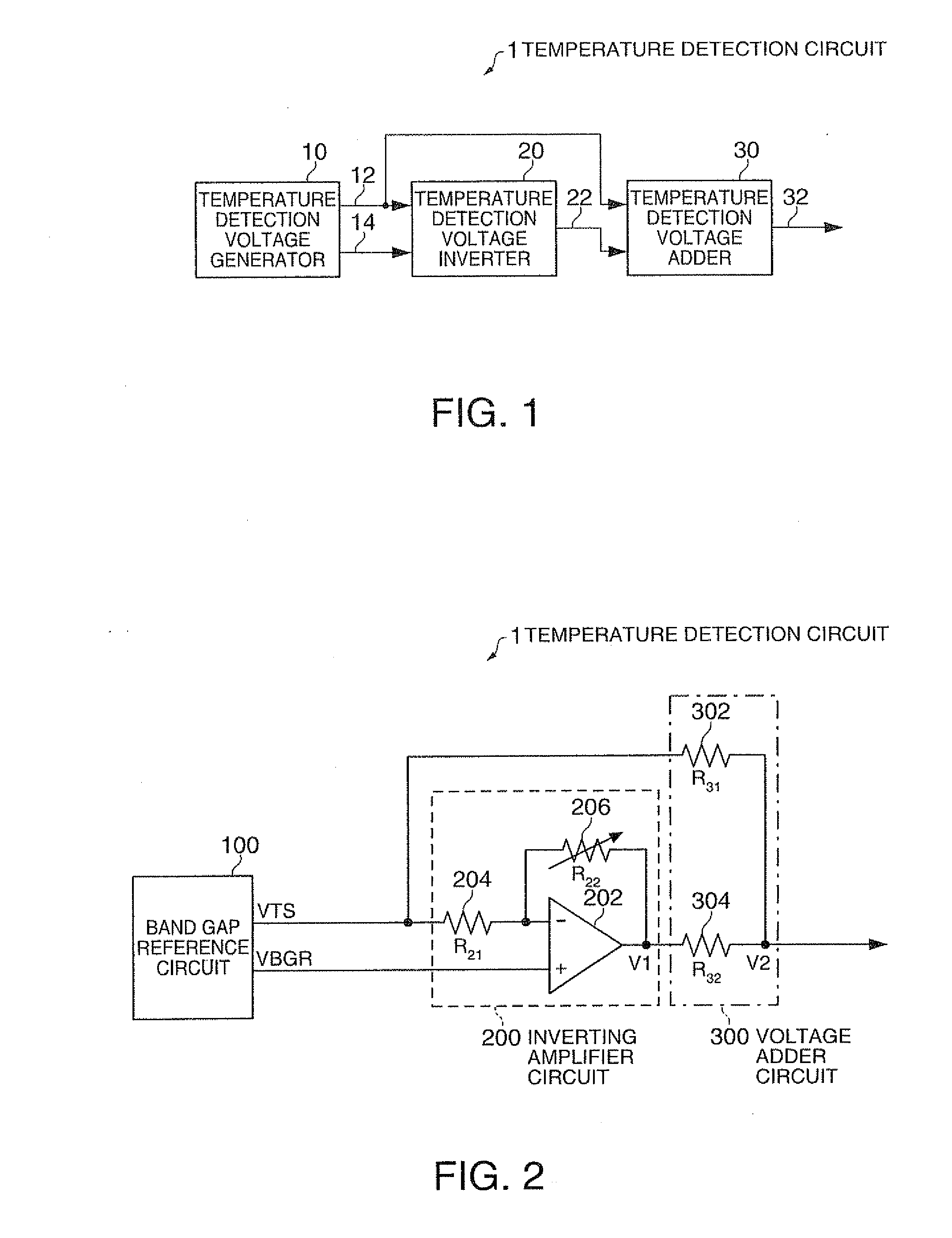
[0032]FIG. 1 is a functional block diagram of a temperature detection circuit of a first embodiment. The temperature detection circuit 1 of the first embodiment includes a temperature detection voltage generator 10, a temperature detection voltage inverter 20, and a temperature detection voltage adder 30. In addition, the temperature detection circuit 1 of the present embodiment may have a configuration in which some of these components (elements) are omitted.

[0033]The temperature detection voltage generator 10 generates a first temperature detection voltage 12 of which the voltage level based on a given reference voltage 14 varies according to the temperature.

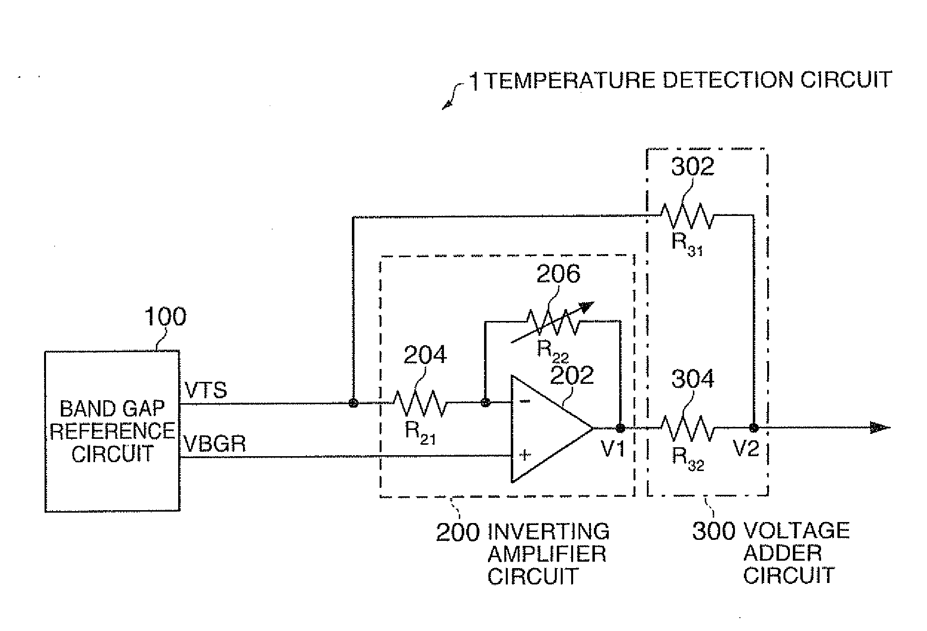
[0034]The temperature detection voltage inverter 20 inverts the reference voltage 14 with reference to the first temperature detection voltage 12, and amplifies or attenuates the reference voltage with a given gain to generate a second temperature detection voltage 22. The gain of the temperature detection ...

second embodiment

(2) Second Embodiment

[0052]FIG. 5 is a functional block diagram of a temperature detection circuit of a second embodiment. The temperature detection circuit 1 of the second embodiment includes the temperature detection voltage generator 10, a temperature detection voltage converter 40, a reference voltage converter 50, the temperature detection voltage inverter 20, and the temperature detection voltage adder 30. In addition, the temperature detection circuit 1 of the present embodiment may have a configuration in which some of these components (elements) are omitted.

[0053]The temperature detection voltage generator 10 generates a first temperature detection voltage 12 of which the voltage level based on a first reference voltage 14 varies according to the temperature.

[0054]The temperature detection voltage converter 40 amplifies or attenuates the first temperature detection voltage 12 on the basis of the first reference voltage 14 so as be converted into a second temperature detecti...


PUM


Abstract

A temperature detection circuit capable of generating a temperature detection voltage with reduced noise level, and a sensor device using the same are provided. The temperature detection circuit includes a temperature detection voltage generator that generates a first temperature detection voltage of which the voltage level based on a reference voltage varies according to the temperature; a temperature detection voltage inverter that inverts the first temperature detection voltage on the basis of the reference voltage, and amplifies or attenuates the first temperature detection voltage to generate a second temperature detection voltage; and a temperature detection voltage adder that adds up the first temperature detection voltage and the second temperature detection voltage.

Description

[0001]The entire disclosure of Japanese Patent Application No. 2011-006818, filed Jan. 17, 2011 is expressly incorporated by reference herein.BACKGROUND[0002]1. Technical Field[0003]The present invention relates to a temperature detection circuit and a sensor device.[0004]2. Related Art[0005]With the advancement of technology in recent years, a variety of sensors is used in various apparatuses and systems. There are digital output and analog output sensors. In the analog output sensors, generally, an output voltage varies according to the detection value on the basis of a voltage (direct-current bias voltage) when a predetermined reference value is detected. For example, in a gyroscope sensor, when there is no input (angular velocity is 0), the direct-current bias voltage is output, and the output voltage varies according to the magnitude of the angular velocity. Generally, this direct-current bias voltage has almost linear characteristics with respect to temperature, and if the tem...

Claims


Application Information

Patent Timeline
IPC IPC(8): G01K7/00
CPCG01C19/5776G01K7/01G01C25/005
Inventor KANAI, MASAHIRO
Owner SEIKO EPSON CORP
Features
  • R&D
  • Intellectual Property
  • Life Sciences
  • Materials
  • Tech Scout
  • Unparalleled Data Quality
  • Higher Quality Content
  • 60% Fewer Hallucinations
Learn More