
Web service system, schedule execution apparatus and control method thereof

a scheduling system and schedule technology, applied in the field of scheduling apparatus, can solve the problems of difficult function enhancement, program complexity, lack of flexibility of the above-mentioned art, etc., and achieve the effect of more flexibility

Active Publication Date: 2012-07-19
CANON KK
View PDF11 Cites 2 Cited by
  • Summary
  • Abstract
  • Description
  • Claims
  • Application Information

AI Technical Summary

Benefits of technology

[0006]At least one embodiment of the present invention is conceived in light of the above-described problems of the conventional art, and makes it possible to execute a particular program according to a schedule more simply, and further, more flexibly.
[0009]With such a configuration, an embodiment of the present invention makes it possible to execute a particular program according to a schedule more simply, and further, more flexibly. In an embodiment, the additional flexibility is achieved by being able to independently control a database apparatus that stores call information, a function providing apparatus that executes a Web service and a schedule executing apparatus that generates messages for calling Web service to be executed according to a schedule. Moreover, in an embodiment, because the database apparatus, the function providing apparatus and the schedule executing apparatus are provided as separate devices in a Web-based system (also referred to herein as “Web service system”), the embodiment provides additional flexibility in terms of physical locations of the devices in that these devices are not required to be present at the same location and can be independently managed and controlled at different locations (i.e., there is no restriction as to the physical location of each device). Furthermore, because the devices are communicably connected to each other in a Web-based system, the embodiment provides additional flexibility in terms of selecting a communication protocol that can be used between the devices.

Problems solved by technology

However, since the program that executes the schedule and the unit that provides the function are inextricably linked, the conventional art described above lacks flexibility and function enhancement is difficult.
Alternatively, in the latter case, because a single program has to provide a plurality of functions, the program may become complicated.

Method used


Image

  • Web service system, schedule execution apparatus and control method thereof
  • Web service system, schedule execution apparatus and control method thereof
  • Web service system, schedule execution apparatus and control method thereof

Examples


first exemplary embodiment

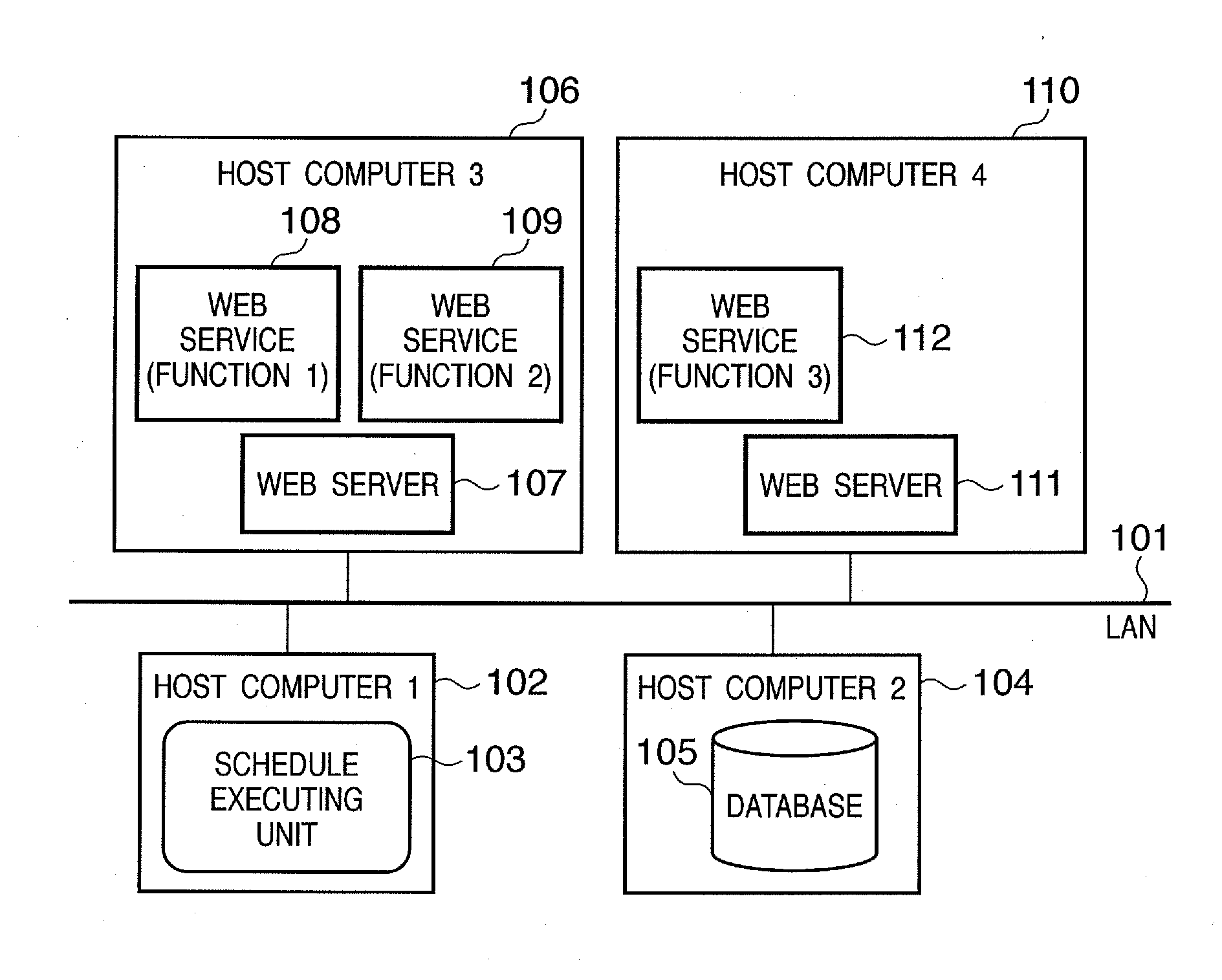
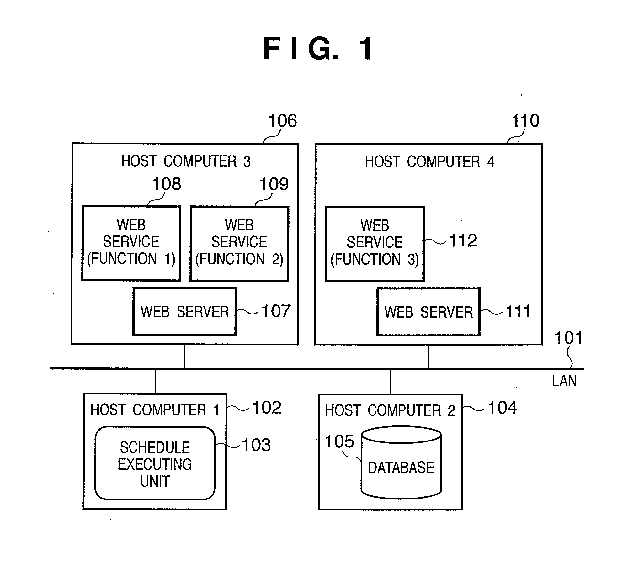
[0023]FIG. 1 is a diagram showing an exemplary configuration of a computer network in which a schedule execution apparatus according to a first embodiment of the present invention can be applied.

[0024]The computer network shown in FIG. 1 comprises a local area network (LAN) 101 to which are connected host computers 1 through 4 (102, 104, 106, 110). A schedule execution unit 103 for calling a function according to a specified schedule runs on host computer 1 (102), which functions as the schedule execution apparatus according to the present embodiment. As described above, the schedule execution unit 103 can be implemented as a program (for example, a resident program called either a daemon or a service) that runs on host computer 1 (102).

[0025]A database 105 operates in host computer 2 (104), and in the database 105 are stored details of the function that the schedule execution unit 103 calls and schedule information. The database 105 is implemented by a database application that use...

second exemplary embodiment

[0050]In the first embodiment, a description was given of a case in which the function call list that describes the process (schedule process) that is to be executed according to a schedule is registered in advance in the database 105. By contrast, in the present embodiment, the user can register new records in the function call list.

[0051]FIG. 5 is a diagram showing an exemplary configuration of a computer network according to a second embodiment of the present invention, in which constituent elements identical to those shown in FIG. 1 are assigned identical reference numerals. In this embodiment, a PC 502 that the user uses is provided in place of the host computer 4 (110) in the configuration shown in FIG. 1. The PC 502 may, for example, be an ordinary computer having the configuration described with reference to FIG. 11. The PC 502 functions as a registration apparatus for registering call information that controls the host computer 1 (102) which functions as the schedule execut...

third exemplary embodiment

[0067]In some cases, a function that searches for a device, such as a computer or a printer, or a router or the like on the network 101 as in the example of the second embodiment, is started and the processing by the called function may not end within a short time period but instead can last several tens of minutes to several hours. With function calls using a Web service, it is desirable that execution results be returned to the Web service caller within a relatively short period of time (usually approximately several tens of seconds). As a result, when carrying out a time-consuming process utilizing a function call that uses a Web service, it is desirable to provide some countermeasure.

[0068]In the present embodiment, a time-consuming process is implemented using the above-described Web service call. In this embodiment as well as with the second embodiment, an example of a function call in the computer network shown in FIG. 5 is described.

[0069]FIG. 8 is a diagram showing an examp...


PUM


Abstract

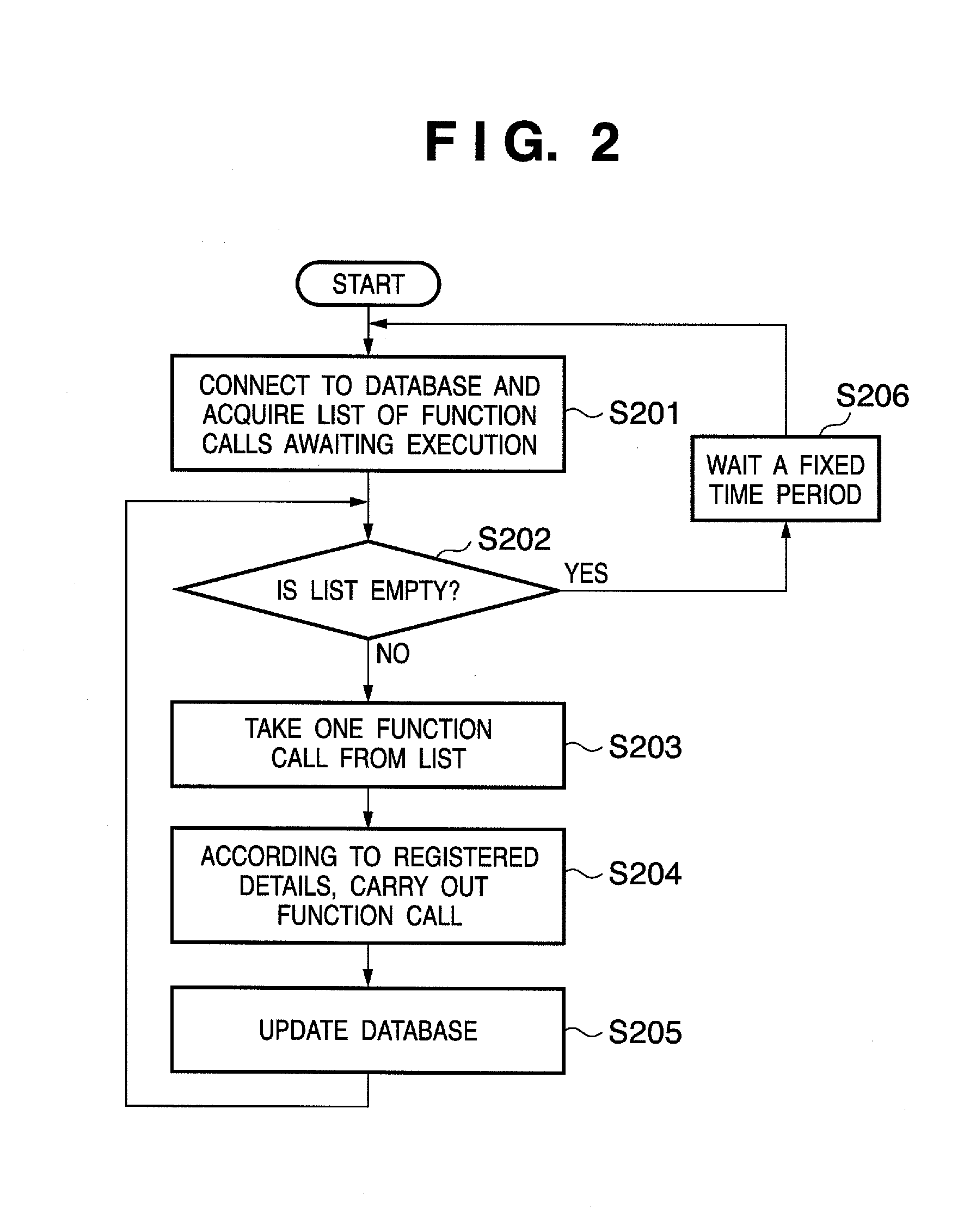
A schedule execution unit accesses a storage unit for storing a call list registered in a database and determines whether or not there is a Web service call to be executed. If the presence of a Web service call to be executed is confirmed, the schedule execution unit reads out the Web service address and process details and calls the Web service. By so doing, the apparatus that provides the function and the apparatus that carries out the call can be separated, thus enabling a particular program to be executed simply and flexibly according to a schedule.

Description

CROSS REFERENCE OF RELATED APPLICATIONS[0001]This application is a Continuation of U.S. patent application Ser. No. 11 / 551,859 filed on Oct. 23, 2006 which claims the benefit of Japanese Patent Application No. 2005-310500, filed on Oct. 25, 2005, which is hereby incorporated by reference herein in its entirety.FIELD OF THE INVENTION[0002]The present invention relates to a schedule execution apparatus for executing a particular program according to a schedule. Additionally, the present invention relates to a registration apparatus for registering information for controlling the schedule execution apparatus. Further, the present invention relates to a function providing apparatus that provides a function that the schedule execution apparatus can call. In addition, the present invention relates to a Web service system that employs a schedule execution apparatus, a function providing apparatus and a database apparatus.BACKGROUND OF THE INVENTION[0003]Conventionally, in computers, functi...

Claims


Application Information

Patent Timeline
Patent Type & Authority Applications(United States)
IPC IPC(8): G06F15/173
CPCG06F9/485H04L67/325G06F9/54G06F9/5027H04L67/62
Inventor NAKAZAWA, TOSHIYUKI
Owner CANON KK
Learn More