Particle sensor, exhaust system and method for determining particles in the exhaust gas

a particle sensor and exhaust gas technology, applied in the field of particle sensor, an exhaust system and a method for determining particles in the exhaust gas, can solve the problems of increasing costs and prohibitive approaches, and achieve the effect of increasing the sensitivity of the particle sensor

Inactive Publication Date: 2012-07-26
FORD GLOBAL TECH LLC
View PDF22 Cites 9 Cited by
  • Summary
  • Abstract
  • Description
  • Claims
  • Application Information

AI Technical Summary

Benefits of technology

[0010]In this way, the original voltage supplied by a battery, for example, may be amplified by the amplifier circuit. In doing so, t

Problems solved by technology

The first approach entails an increase in costs which is not justified merely by a certain requirement of measurement, wherein the second approach may be prohibitive

Method used


Image

  • Particle sensor, exhaust system and method for determining particles in the exhaust gas
  • Particle sensor, exhaust system and method for determining particles in the exhaust gas
  • Particle sensor, exhaust system and method for determining particles in the exhaust gas

Examples


Embodiment Construction

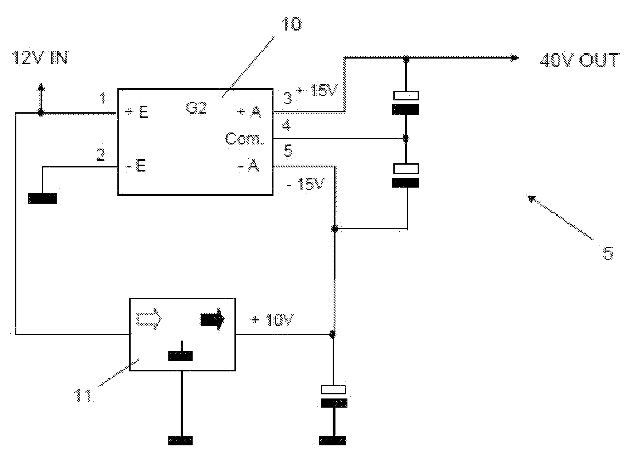
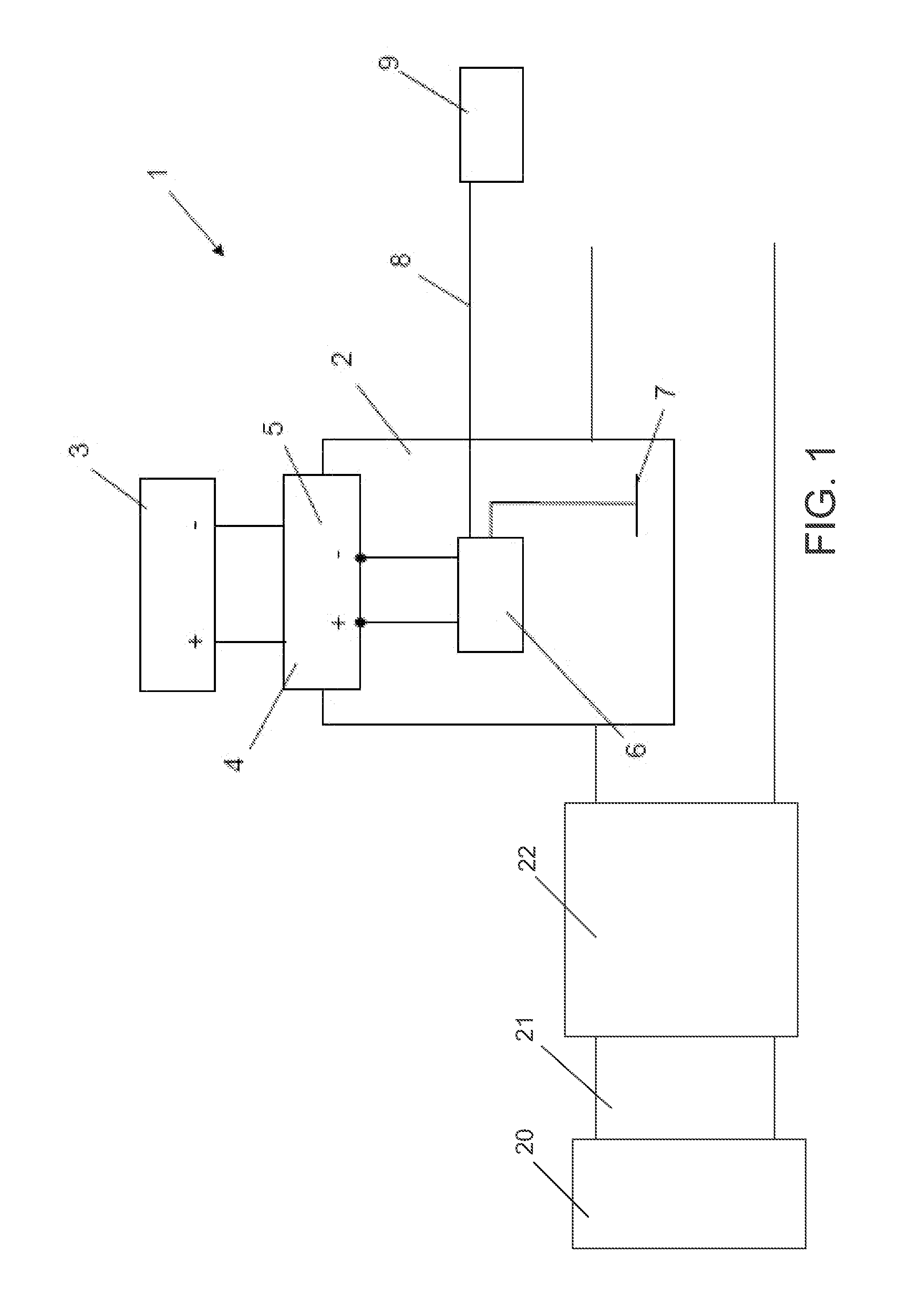
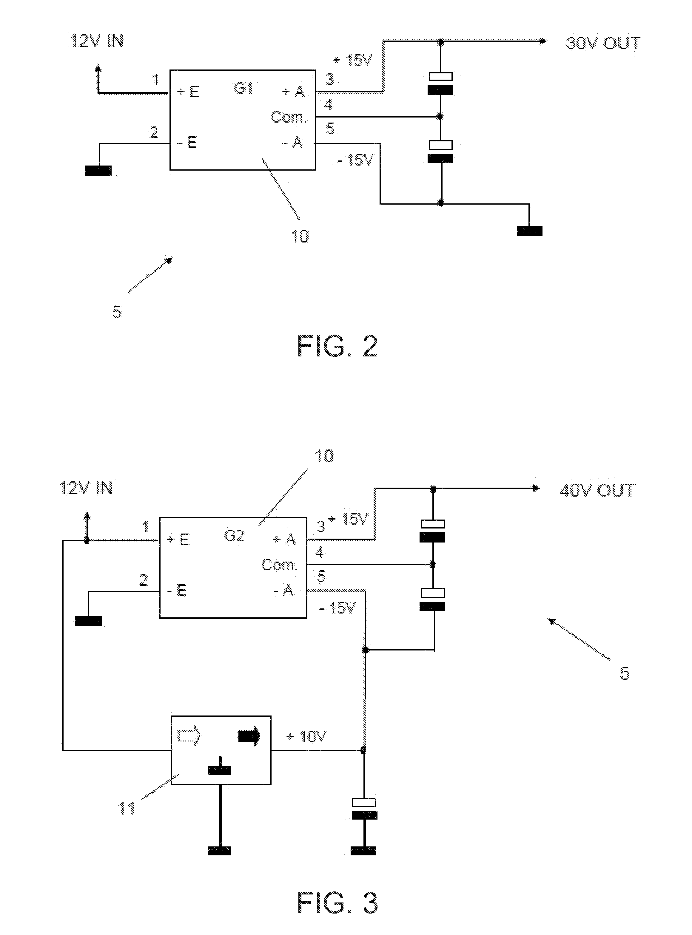
[0018]According to a first aspect of the disclosure, a particle sensor for an exhaust system comprises a sensor element and an integrated amplifier circuit for amplifying a reference voltage for the sensor element.

[0019]In general, the particle or solid body sensor may be used in the exhaust system to detect solid and also soluble fractions in the exhaust-gas flow. For this purpose, use is conventionally made of a resistance element whose resistance varies when substances from the exhaust gas precipitate on the sensor element. This requires regular regeneration of the sensor by periodically increasing the temperature of the sensor element in order to evaporate the accumulated material. The derivative of the sensor signal with respect to time may be used to calculate the mass throughflow of the solid or soluble materials in the exhaust gas. Such a sensor concept may also be considered to be a means for the detection of a leak of a particle filter if soot emissions downstream of the f...


PUM


Abstract

A particle sensor for exhaust system is provided. In one embodiment, the particle sensor comprises a sensor element and an integrated amplifier circuit for amplifying a reference voltage for the sensor element. In this way, the particle sensor may provide increased sensitivity.

Description

RELATED APPLICATIONS[0001]The present application claims priority to German Patent Application No. 102011002937.0, filed on Jan. 20, 2011, the entire contents of which are hereby incorporated by reference for all purposes.FIELD[0002]The disclosure relates to a particle sensor, an exhaust system and a method for determining particles in the exhaust gas.BACKGROUND AND SUMMARY[0003]To monitor an exhaust system of an internal combustion engine, use is made of particle sensors which measure the particle content of the exhaust gases flowing through the exhaust system.[0004]At present, resistive particle sensors are known in which two or more metallic electrodes are formed. The particles, in particular soot particles, that are accumulated cause the electrodes, which engage into one another in a comb-like manner, to be short-circuited, and therefore, with increasing particle concentration on the sensor surface, a decreasing resistance or a decreasing impedance (or an increasing current if a...

Claims


Application Information

Patent Timeline
IPC IPC(8): G01N33/497
CPCG01N15/0656
Inventor YACOUB, YASSER M.HAVENITH, GUIDO
Owner FORD GLOBAL TECH LLC
Why Eureka
Try Eureka