Method and system for non-destructive testing

a non-destructive testing and method technology, applied in the field of methods and systems for non-destructive testing, can solve the problems of difficult conventional methods to detect obscure closed cracks, and achieve the effect of higher accuracy

Inactive Publication Date: 2012-07-26
KYUSHU UNIV
View PDF4 Cites 9 Cited by
  • Summary
  • Abstract
  • Description
  • Claims
  • Application Information

AI Technical Summary

Benefits of technology

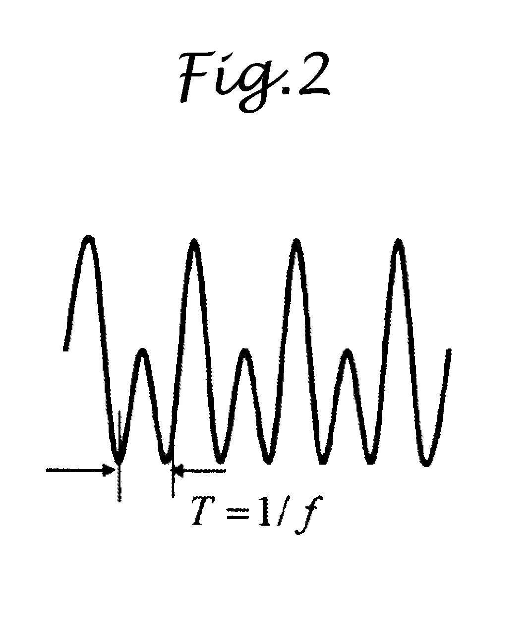
[0013]In the non-destructive testing method of the present invention, the condition of an object to be tested is diagnosed based on the temporal change of the instantaneous frequency. According to the inventor's study, the frequency of the attenuation waveform of the single-pulse ultrasonic wave signal, which has transmitted obscure cracks, tends to decrease. It is possible to discover an abnormal condition by observing the temporal change of the instantaneous frequency of the attenuation waveform of the single-pulse ultrasonic wave signal. Such abnormal condition could not be found by conventional methods using a single-pulse ultrasonic wave signal. The method of the present invention uses a single-pulse ultrasonic wave signal. Therefore, the method of the present invention is hardly affected by interference of reflected waves and is capable of detecting even a small amount of frequency change. In addition, the method of the present invention is higher in accuracy than conventional methods of detecting harmonic and sub-harmonic components.
[0016]When using wavelet or Hilbert transform, the envelope line A(t) and the phase φ(t) of the attenuation waveform of a single-pulse ultrasonic wave signal having as small as one or two periods may be obtained readily and accurately.
[0017]A non-destructive testing system of the present invention comprises a pulse entering section configured to enter a single-pulse ultrasonic wave signal into an object to be tested; a receiving section configured to receive the single-pulse ultrasonic wave signal which has been entered into the object to be tested; a temporal change computing section configured to compute temporal change of an instantaneous frequency of an attenuation waveform of the received single-pulse ultrasonic wave signal; and a diagnosing section configured to diagnose a condition of the object to be tested, based on the temporal change of the instantaneous frequency computed by the temporal change computing section. The diagnosing section stores the temporal change of an instantaneous frequency, which have been measured in advance in respect of the object known to be in a normal condition, as at least one criterion for diagnosis. Then, the diagnosing section diagnoses the condition of the object to be tested by comparing the temporal change of the instantaneous frequency computed by the temporal change computing section with the at least one criterion for diagnosis. Since the non-destructive testing system of the present invention performs diagnosis by looking into the instantaneous frequency of the attenuation waveform of the single-pulse ultrasonic wave signal, the system is hardly affected by interference of reflected waves and is capable of detecting even a small amount of frequency change. In addition, the system of the present invention is higher in accuracy than conventional apparatuses of detecting harmonic and sub-harmonic components.

Problems solved by technology

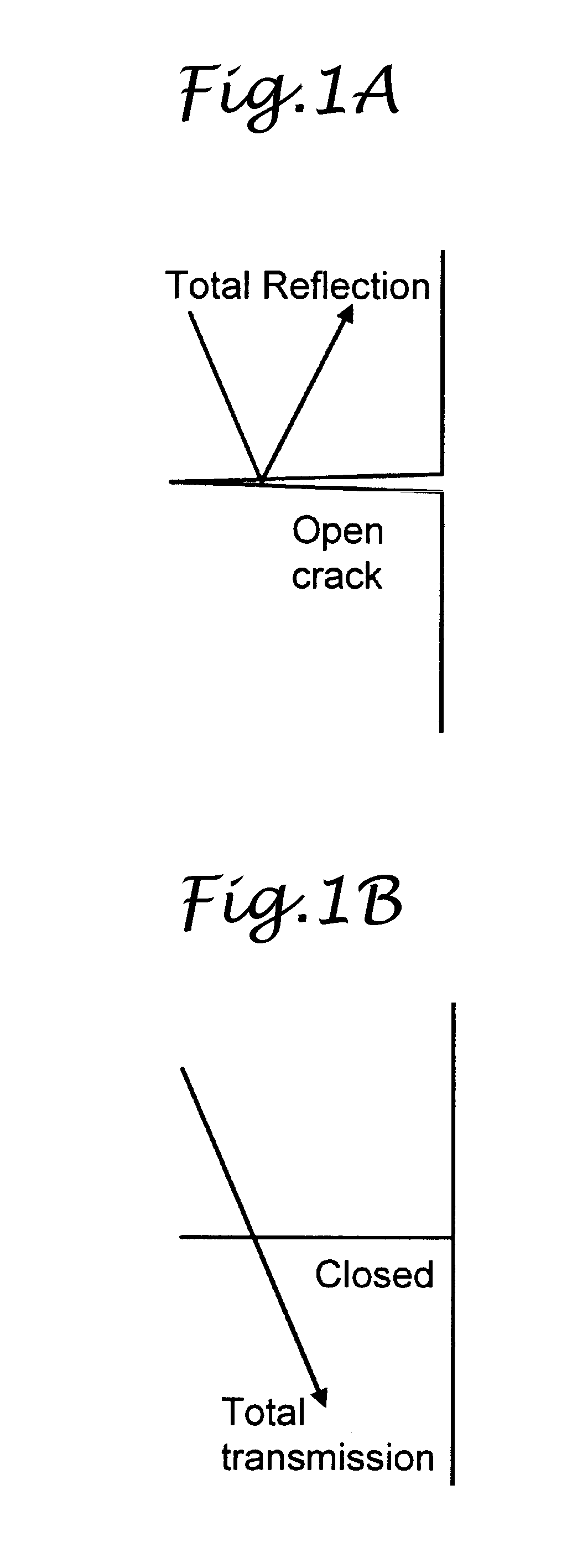
It is difficult by the conventional methods to detect obscure closed cracks as shown in FIG. 1B since the ultrasonic wave transmits such cracks.

Method used


Image

  • Method and system for non-destructive testing
  • Method and system for non-destructive testing
  • Method and system for non-destructive testing

Examples


Embodiment Construction

[0032]Now, embodiments of a method and a system for non-destructive testing according to the present invention will be described in detail with reference to the accompanying drawings. FIG. 3 illustrates an example configuration of a non-destructive testing system of the present invention. Reference numeral 1 designates an object to be tested that is made of two rubber plates joined together. In this embodiment, a pulse entering section 2 configured to enter a single-pulse ultrasonic wave signal and a receiving section 3 configured to receive the incident single-pulse ultrasonic wave signal (or the single-pulse ultrasonic wave signal which has been entered into the object to be tested) are disposed to sandwich the object to be tested therebetween. An ultrasonic wave oscillator 4 transmits a pulse signal having a frequency of 1 MHz to 10 MHz and one or two periods to the pulse entering section 2. The pulse entering section 2 enters the single-pulse ultrasonic wave signal into the obje...


PUM

PropertyMeasurementUnit
frequencyaaaaaaaaaa
angular frequencyaaaaaaaaaa
instantaneous frequencyaaaaaaaaaa

Abstract

Provided herein is a non-destructive testing method capable of diagnosing a condition of an object to be tested using a single-pulse ultrasonic wave signal. An attenuation waveform of the single-pulse ultrasonic wave signal received by a receiving section 3 is wavelet transformed by a wavelet transform section 6 to obtain an envelope line A(t) and a phase φ(t) of the attenuation waveform. A temporal change computing section 7 approximates the attenuation waveform by an approximation equation available for computation, using the envelope line A(t) and the phase φ(t) of the attenuation waveform inputted from the wavelet transform section 6, and obtains the temporal change of instantaneous frequency of the attenuation waveform. A diagnosing section 8 diagnoses a condition of the object to be tested, based on the temporal change of the instantaneous frequency computed by the temporal change computing section 7.

Description

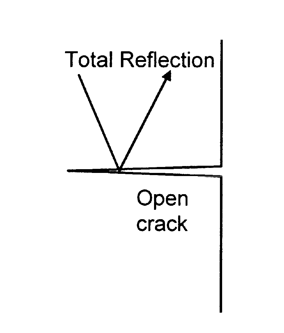
TECHNICAL FIELD[0001]The present invention relates to a method and a system for non-destructive testing using an ultrasonic wave pulse.BACKGROUND ART[0002]Japanese Patent No. 3705960 (Patent Document 1) shows conventional ultrasonic testing. In conventional ultrasonic testing methods for diagnosis of abnormality or abnormal conditions, an ultrasonic wave, which has been entered into an object to be tested and reflected on a discontinuous or discrete interface, namely an abnormal portion, is measured in terms of a pulse (see FIG. 1A).[0003]Japanese Patent Application Publication No. 2004-340807 (JP 2004-340807A) (Patent Document 2) discloses an ultrasonic testing method for detecting minute abnormality such as defects due to insufficient weld by entering an ultrasonic wave into the surface of contact and evaluating waveform distortion of a transmitted wave with respect to the incident wave. In this disclosure, the waveform of the transmitted wave is frequency analyzed with respect to...

Claims


Application Information

Patent Timeline
Patent Type & Authority Applications(United States)
IPC IPC(8): G01N29/11
CPCG01N29/343G01N29/4454G01N2291/102G01N2291/044G01N29/46
Inventor INOUE, TAKUMI
Owner KYUSHU UNIV
Why Eureka
Try Eureka