Variable valve timing device

a timing device and variable valve technology, applied in valve arrangements, mechanical equipment, machines/engines, etc., can solve the problems of hysteresis adversely affecting the response characteristic of the control valve, etc., to reduce hysteresis, reduce side force, and small resistance

Active Publication Date: 2012-07-26
DENSO CORP
View PDF5 Cites 23 Cited by
  • Summary
  • Abstract
  • Description
  • Claims
  • Application Information

AI Technical Summary

Benefits of technology

[0006]According to the bias adjusting means disclosed in 3P2010-163942A, the cylindrical movable member is supported from a radial outside by the sleeve, and is kept apart from the spool in a radial outside direction. Therefore, in the second region where the movable member rests on the sleeve, since the spool can move relative to the movable member without contacting the movable member in a radial direction, the spool receives only a small movement resistance. As shown in FIG. 21, which shows a relationship between a spool position and the instruction value to the driving source, in the second region, there may be a small amount of hysteresis between a movement in an axial forward direction Dg and a movement in an axial reverse direction Dr. Contrary, in the first region where the movable member and the spool are axially engaged to move together, the spool receives a sliding resistance which the movable member generates by coming in contact with the sleeve in the radial direction and sliding on the sleeve. At this movement, the movable member moves while receiving the second restoring force from the second resilient member. Therefore, if an acting direction of the second restoring force inclines to the axial direction of the sleeve, the movable member may receive a side force in the radial direction and be easily pushed onto the sleeve located on the radial outside. Such force pushing the movable member onto the sleeve may be generated therebetween and increases the sliding resistance which increases a movement resistance of the spool. As a result, in the first region, the sliding resistance may act on the spool in both moving directions. As shown in FIG. 21, in the first region, there may be a large amount of hysteresis between a movement in an axial forward direction Dg and a movement in an axial reverse direction Dr. As a result, the large hysteresis adversely affects the response characteristic of the control valve. In another aspect, the sliding resistance between the movable member and the sleeve may be changed irregularly as the spool moves. This causes the spool to move intermittently. In other words, a stick-slip phenomenon on the spool movement may be easily occurred. As a result, the irregularly changing sliding resistance adversely affects the response characteristic of the control valve.
[0008]It is another object of the present invention to provide a variable valve timing device having a control valve which can suppress a variation in the response characteristic.
[0011]The movable member is apart from the sleeve in a radial direction. Therefore, the spool can move with a small resistance in the first region in which the spool and the movable member are engaged. As a result, it is possible to reduce a hysteresis between a forward movement and a reverse movement. In the second region, the spool may move in a sliding manner on the movable member that rests on the sleeve. However, the movable member can be held stable on the sleeve. Therefore, it is possible to reduce a side force that could push the movable member onto the spool. As a result, it is possible to reduce sliding resistance acting on the spool in the second region, and to reduce a hysteresis between a forward movement and a reverse movement. In addition, since a fluctuation of friction between the spool and the movable member is reduced to a sufficiently low level, it is possible to suppress a stick-slip in the second region. As a result, it is possible to provide the variable valve timing device having the control valve with a stable response characteristic.

Problems solved by technology

As a result, the large hysteresis adversely affects the response characteristic of the control valve.
As a result, the irregularly changing sliding resistance adversely affects the response characteristic of the control valve.

Method used


Image

  • Variable valve timing device
  • Variable valve timing device
  • Variable valve timing device

Examples


first embodiment

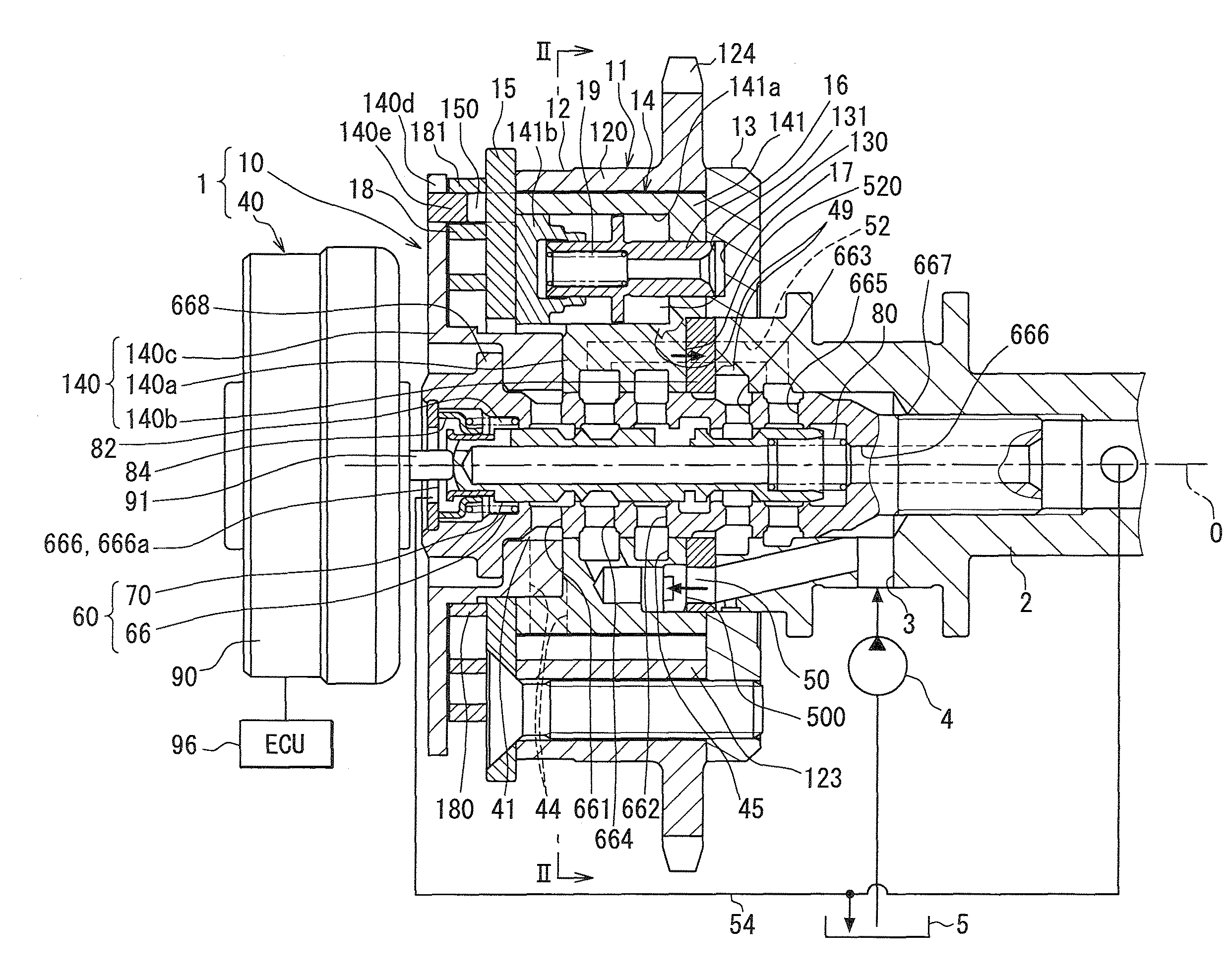
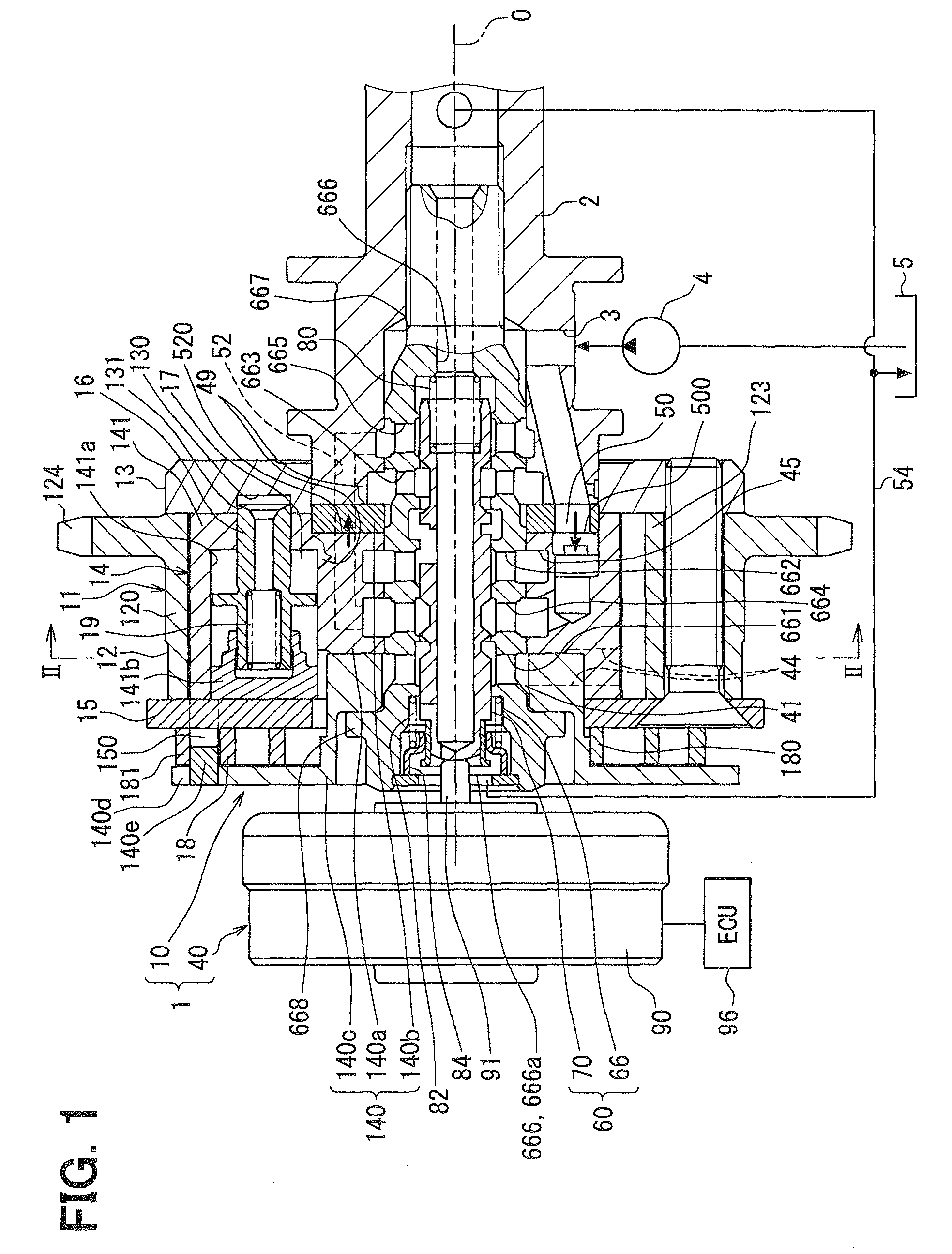
[0039]FIG. 1 shows a first embodiment in which a variable valve timing device 1 is applied to an internal combustion engine for a vehicle. The variable valve timing device 1 is a fluid driven type which uses oil as hydraulic fluid, and adjusts valve timing of an inlet valve assumed as a valve.

[0040](Basic Components)

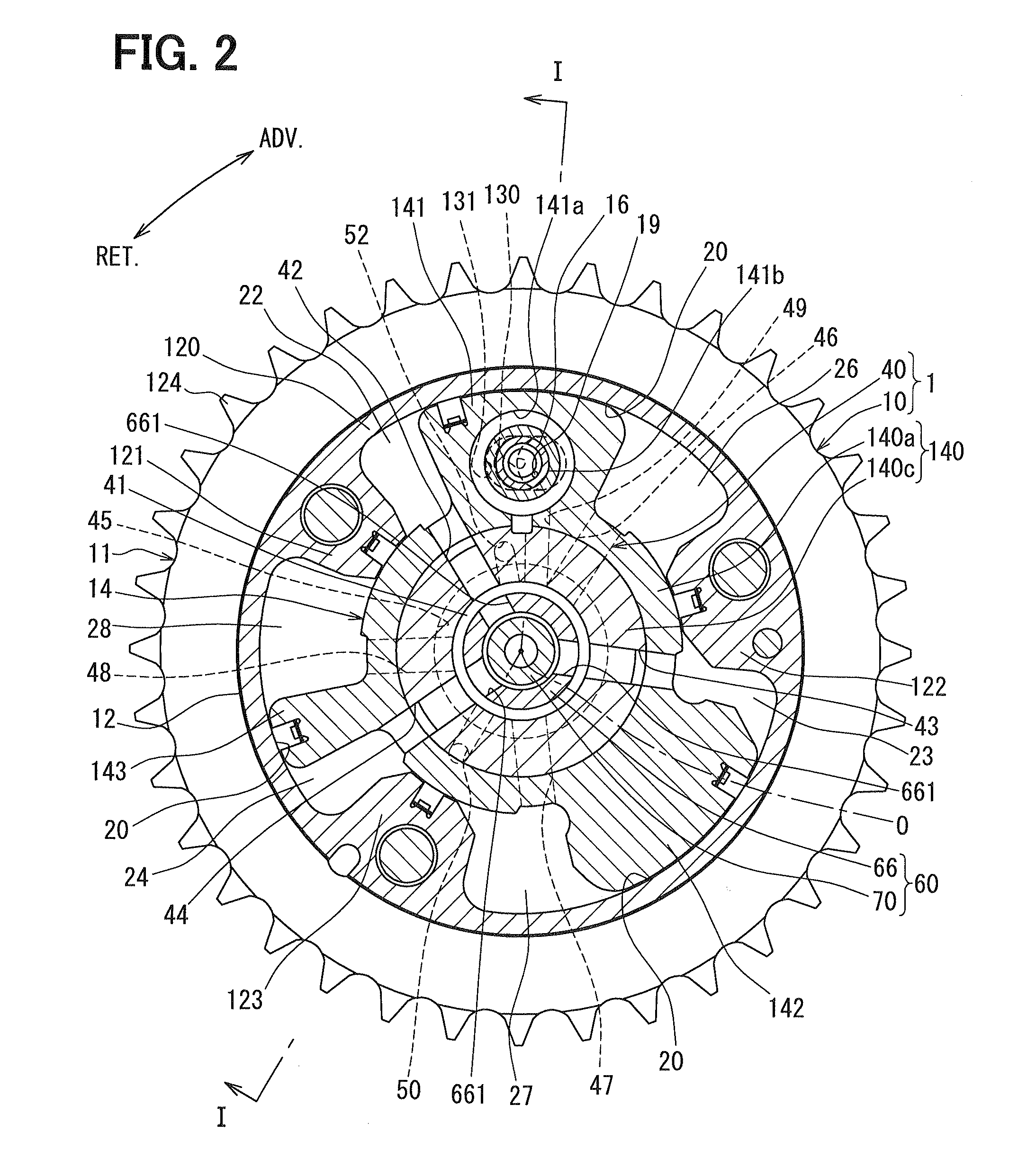
[0041]First, the basic components of the variable valve timing device 1 are explained. As shown in FIGS. 1 and 2, the variable valve timing device 1 includes a rotary-mechanism part 10 and a control part 40. The rotary-mechanism part 10 is disposed in a transmission system which transmits an engine torque outputted from a crankshaft (not shown) to the cam shaft 2 in the internal combustion engine. The control part 40 controls in-flow and out-flow of the hydraulic oil for driving the rotary-mechanism part 10.

[0042](Rotary Mechanism Part)

[0043]In the rotary-mechanism part 10, the housing 11 is formed by placing and tightening a rear plate 13 and a front plate 15 on both ax...

second embodiment

[0116]As shown in FIG. 13, the second embodiment is a modification of the first embodiment.

[0117](Drive Mechanism)

[0118]Hereafter, components of a control valve 260 in the second embodiment that are different from the first embodiment are mainly explained. As shown in FIGS. 13-17, the biasing device includes a first resilient member 80 and a second resilient member 282. The second resilient member 282 made of a metal compression coil spring is coaxially accommodated in the drain port 666a of the sleeve 266 disposed within the rotary components 2, 14. The second resilient member 82 is deformed by compressing it by disposing it between the stopper 660 fixed on the drain port 666a and the movable member 284. Thereby, the second resilient member 282 generates a second restoring force F2 which pushes and biases the movable member 284 in the axial forward direction Dg. The second resilient member 82 generates the second restoring force F2 for pushing the movable member 284 in the axial di...


PUM


Abstract

A variable valve timing device includes a control valve for switching fluid communication among ports. The control valve includes a sleeve, a spool, a movable member, and resilient members. A first resilient member pushes the spool in both of the regions. A second resilient member acts on the spool via the movable member engaged with the spool in an advancing region. In a lock region, the movable member rests on the sleeve to enable the spool to move freely from the second resilient member. As a result, force acting on the spool can be restricted in the lock region. The movable member is supported from a radial inside by the spool and is radially distanced from the sleeve. As a result, it is possible to reduce a sliding resistance acting on the movable member.

Description

CROSS REFERENCE TO RELATED APPLICATION[0001]This application is based on Japanese Patent Application No. 2011-10097 filed on Jan. 20, 2011, the contents of which are incorporated herein by reference in its entirety.FIELD OF THE INVENTION[0002]The present invention relates to a variable valve timing device for adjusting a valve timing of a valve, which is opened and closed by a camshaft driven by a torque transmitted from a crankshaft of the internal combustion engine.BACKGROUND OF THE INVENTION[0003]Conventionally, several kinds of variable valve timing devices (VVT) are known in this field. For example, a vane type VVT has a housing and a vane rotor relatively rotatable to the housing. The housing is adapted to be rotated with one of a crankshaft and a cam shaft. The vane rotor is housed in the housing and is adapted to be rotated with the other one of the crankshaft and the cam shaft. JP2010-163942A discloses a device that varies a relative rotational phase of the vane rotor with ...

Claims


Application Information

Patent Timeline
Patent Type & Authority Applications(United States)
IPC IPC(8): F01L1/34
CPCF01L1/3442F01L2001/34469F01L2001/34456F01L2001/34433
Inventor FUJIYOSHI, TOSHIKITAKENAKA, AKIHIKO
Owner DENSO CORP
Why Eureka
Try Eureka