Exhaust valve

Inactive Publication Date: 2012-07-26
TOYOTA JIDOSHA KK
View PDF0 Cites 2 Cited by
  • Summary
  • Abstract
  • Description
  • Claims
  • Application Information

AI Technical Summary

Benefits of technology

[0013]The object of the present invention is to provide an exhaust valve that has adequate strength in high temperature without increase of weight or manufacturing cost.
[0015]With the above structure, in the exhaust valve according to the aspect, the effect can be obtained such that the adequate strength in high temperature can be secured without weight increase or increase in the manufacturing cost. That is, the exhaust valve according to the present aspect is formed to have a larger shaft diameter of the thick shaft section only that requires the strength in high temperature in a specified section, and therefore problems in the conventional exhaust valve can be solved in which the weight is increased by thickening the diameter of the entire valve stem to improve the strength in high temperature. In addition, because the exhaust valve according to the present aspect is made of a general-purpose inexpensive material, rare metals that have high strength in high temperature are not required as the conventional exhaust valve, the metals of high material cost are not used, and therefore the increase in the manufacturing cost can be prevented. Because the exhaust valve according to the present aspect does not require the addition or the change of the heat treatment to improve the strength in high temperature, the heat treatment process is not required to be added or changed in manufacturing processes as the conventional exhaust valve, and therefore the increase in the costs for equipment itself or change of equipment can be prevented. Because the strength in high temperature can be improved as described above, if the temperature of the exhaust gas that is flown from the combustion chamber increases due to the improvement of fuel efficiency or requirements such as exhaust emission control in the future, the exhaust valve that has high mechanical strength can be obtained without the increase of weight or manufacturing cost. In addition, an effect on mobility of the exhaust valve can be reduced, and good movement characteristics can be obtained.
[0016]According to the present invention, an exhaust valve that has adequate strength in high temperature can be provided without increase of weight or manufacturing cost.

Problems solved by technology

On the other hand, the strength of the smaller diameter portion against the stress concentration is adequately compensated with its curved surface shape; however, strength in high temperature is not taken into consideration.
As a result, there are problems that due to high temperature exhaust gas which flows through the smaller diameter portion, the smaller diameter portion reaches high temperature, mechanical strength deteriorates, and the strength in high temperature is inadequately compensated.
However, when the cross-sectional area of the valve stem is expanded, weight of the valve stem increases, and kinematical performance of a valve lift mechanism decreases.
Thus, usage rotational speed of the valve lift mechanism has to be reduced, and it causes the deterioration of marketability of the product.
Therefore, exhaust gas flow is hindered, and it results in performance degradation of the internal combustion engine or poor fuel efficiency.
However, when metals that have high strength in high temperature such as rare metals that include nickel (Ni), chromium (Cr), and molybdenum (Mo) are used for the valve stem, although the strength in high temperature improves, the metals of high material cost are used for a part for which relatively high strength in high temperature is not required, and therefore manufacturing cost may increase.
However, when the addition and the change of the heat treatment are made to the valve stem, a heat treatment process is required to be added or changed in manufacturing processes, and therefore costs for equipment itself or change of equipment may increase.
In this case, because the entire valve stem is placed in a furnace to be heat-treated, a part for which relatively high strength in high temperature is not required is subjected to heat treatment, and therefore manufacturing cost may increase.
Accordingly, even though any measures to improve the strength in high temperature are taken, there has been a problem that the measures are inadequate.

Method used


Image

  • Exhaust valve
  • Exhaust valve
  • Exhaust valve

Examples


Embodiment Construction

[0024]Hereinafter, embodiments in which the exhaust valve according to the present invention is applied to a valve train of an internal combustion engine are described with reference to the attached drawings.

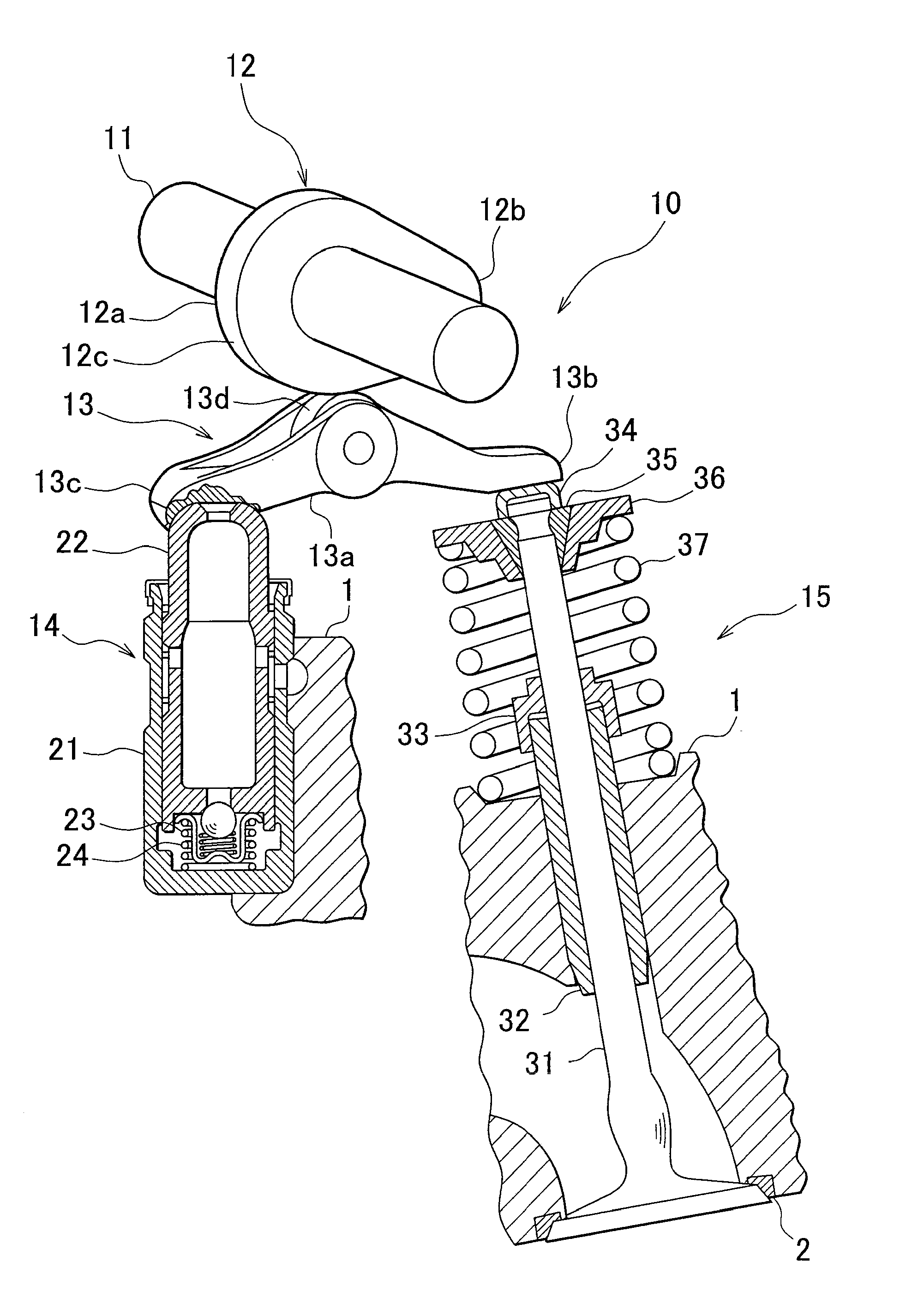
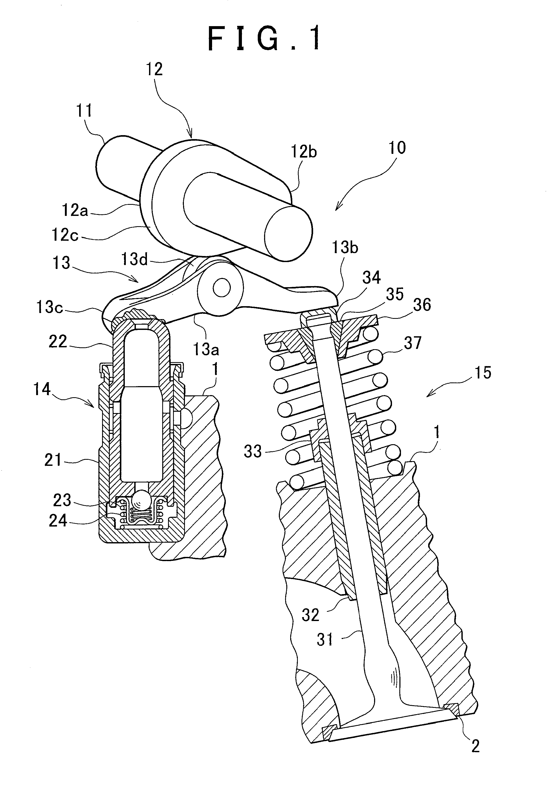
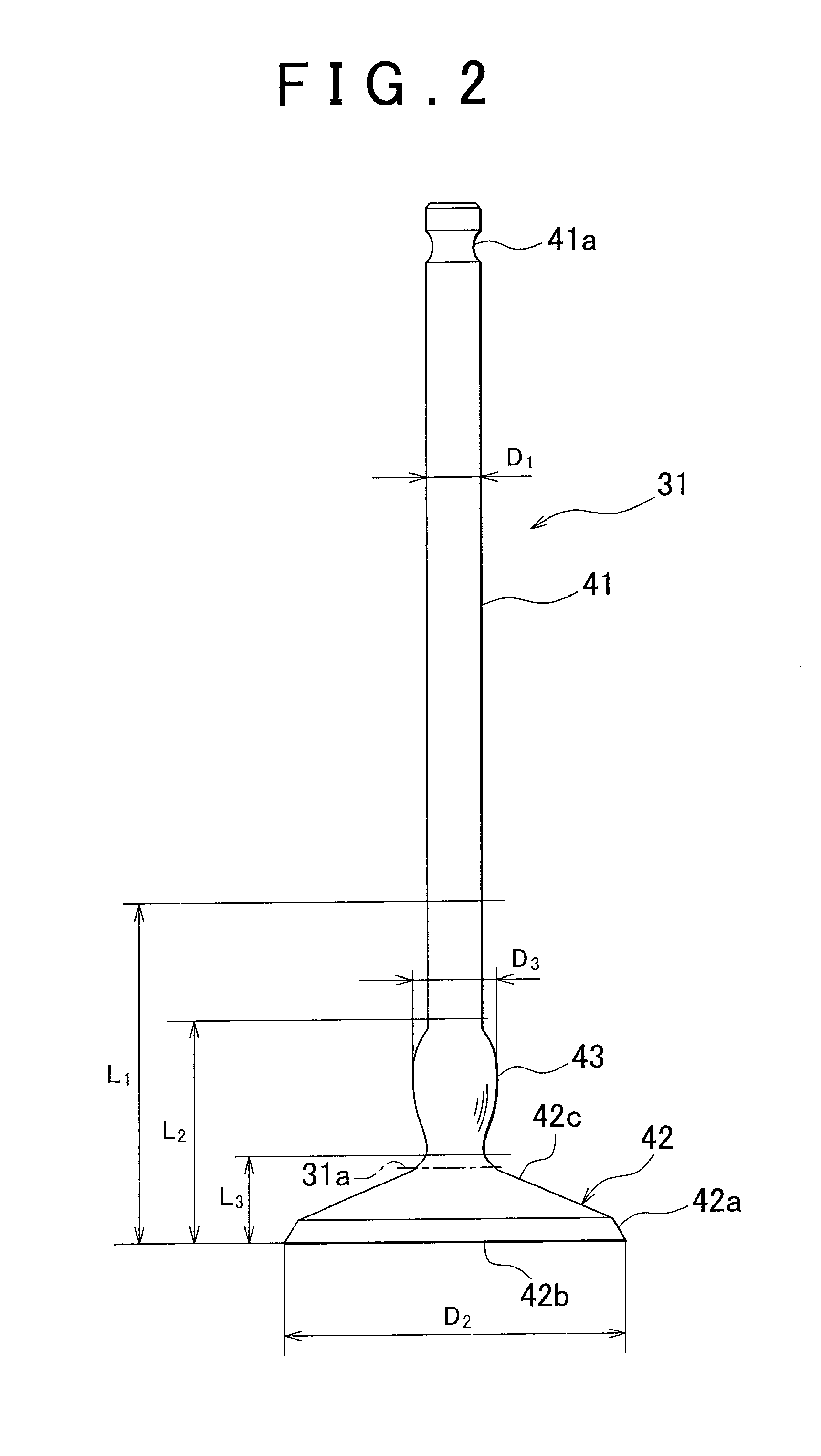
[0025]First, structure of the valve train is described. As shown in FIG. 1, the exhaust valve 31 according to the embodiment of the present invention constitutes a part of the valve train 10 of the internal combustion engine, and the exhaust valve 31 is described through the description of the valve train 10.

[0026]The valve train 10 includes a camshaft 11, a cam 12 that is provided on the camshaft 11, a rocker arm 13 that is engaged with the cam 12, a lash adjuster 14 that is engaged with a first end of the rocker arm 13, and a valve lift mechanism 15 that is engaged with a second end of the rocker arm 13. This valve train 10 is mounted in a cylinder head 1 of the internal combustion engine (not shown).

[0027]In this valve train 10, the rocker arm 13 rotates to the second end of ...


PUM


Abstract

An exhaust valve includes: a shaft section; and a head section that is formed in one end of the shaft section and formed with a valve face that seats on a valve seat disposed in a cylinder head of an internal combustion engine, in which the shaft section has a shaft diameter of a constant diameter; the head section has a head diameter that is larger than the shaft diameter; and a thick shaft section that has a diameter smaller than the head diameter and larger than the shaft diameter is formed within a section between a connecting position that connects the shaft section with the head section and a position that is spaced apart from the head front surface opposite to the valve face in an axial direction by a distance that is approximately the same as the head diameter.

Description

INCORPORATION BY REFERENCE[0001]The disclosure of Japanese Patent Application No. 2011-009949 filed on Jan. 20, 2011 including the specification, drawings and abstract is incorporated herein by reference in its entirety.BACKGROUND OF THE INVENTION[0002]1. Field of the Invention[0003]The present invention relates to an exhaust valve of an internal combustion engine, and more particularly to an exhaust valve that can improve mechanical strength.[0004]2. Description of the Related Art[0005]Conventionally, an exhaust valve of such the type is well-known in the related art which includes a valve main part, a valve guide, and a valve stem that has a smaller diameter portion on the side of the valve main part and a larger diameter portion on the side spaced from the valve main part, in which a boundary between the smaller diameter portion and the larger diameter portion is formed in a smoothly curved surface, and a part of the smoothly curved surface is positioned so as to enter into the v...

Claims


Application Information

Patent Timeline
IPC IPC(8): F01L3/00
CPCF01L3/00F01L1/2405F01L1/185
Inventor SUGIMOTO, SHINSUKESHOJI, JUNPEI
Owner TOYOTA JIDOSHA KK
Why Eureka
Try Eureka