
Electronic smoke

Active Publication Date: 2012-07-26
AKRIA CLIENT SERVICES LLC
View PDF19 Cites 146 Cited by
  • Summary
  • Abstract
  • Description
  • Claims
  • Application Information

AI Technical Summary

Benefits of technology

[0006]According to the present invention, there is provided an electronic smoke comprising an inhale detector and a smoke effect generating circuitry, wherein the inhale detector comprises an air-flow sensor which is arranged to detect direction and rate of air flow through the smoke apparatus, and wherein the smoke effect generating circuitry is arranged to operate the smoke effect generating circuitry to generate smoking effect when the air flow direction corresponds to inhaling through the apparatus and the air flow rate reaches at predetermined threshold. Such an electronic smoke alleviates the problem of inadvertent triggering due to environmental vibration or noise or children playing by blowing into the device.
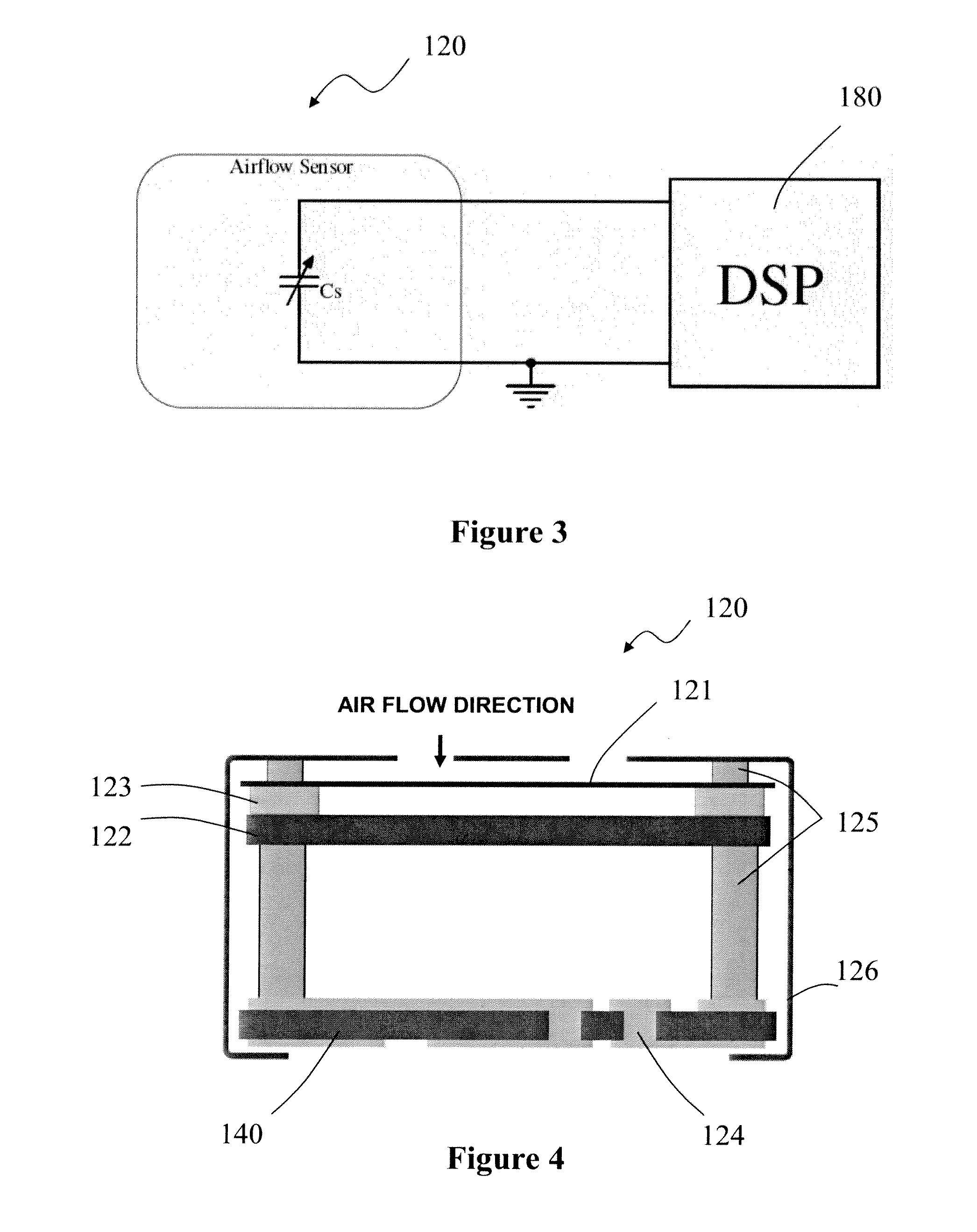
[0007]In an embodiment, the air-flow sensor may comprise an air-baffle surface which is adapted to deform in response to movement of air through the apparatus, the extent of deformation of the air-baffle surface being measured to determine both the direction and rate of air flow through the apparatus. Measure of deformation within a predetermined period of time further mitigates the risk of inadvertent triggering due to vibrations or environmental noise.
[0010]As a further example, the air-flow sensor may form part of an oscillator circuit, and the processor is arranged to measure the oscillation frequency of the oscillation circuit to determine the air-flow rate and direction. As the oscillation frequency of an oscillator circuit, especially an LC oscillator circuit, is dependent on the capacitance value, this provides a cost effective solution to provide a low cost and compact solution.
[0011]As an example, the predetermined threshold of air flow rate may correspond to the flow rate of a typical smoke inhaling action by a user through the apparatus. This would operate to prevent triggering of the smoke generating circuitry by mischief or accidental vibration or noise.

Problems solved by technology

However, such an arrangement is not very reliable since false actuations are common, especially in a noisy environment.
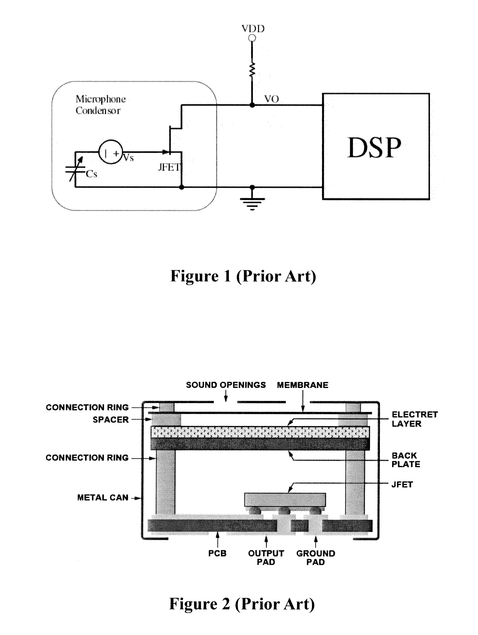
Furthermore, the structure of a conventional air-flow sensor is relatively complicated and more expensive, since a JFET stage is required to amplify signals detected by the vibrating membrane and an electret layer is in combination with a back plate to form a reference capacitive surface.

Method used


Image

  • Electronic smoke
  • Electronic smoke
  • Electronic smoke

Examples


Embodiment Construction

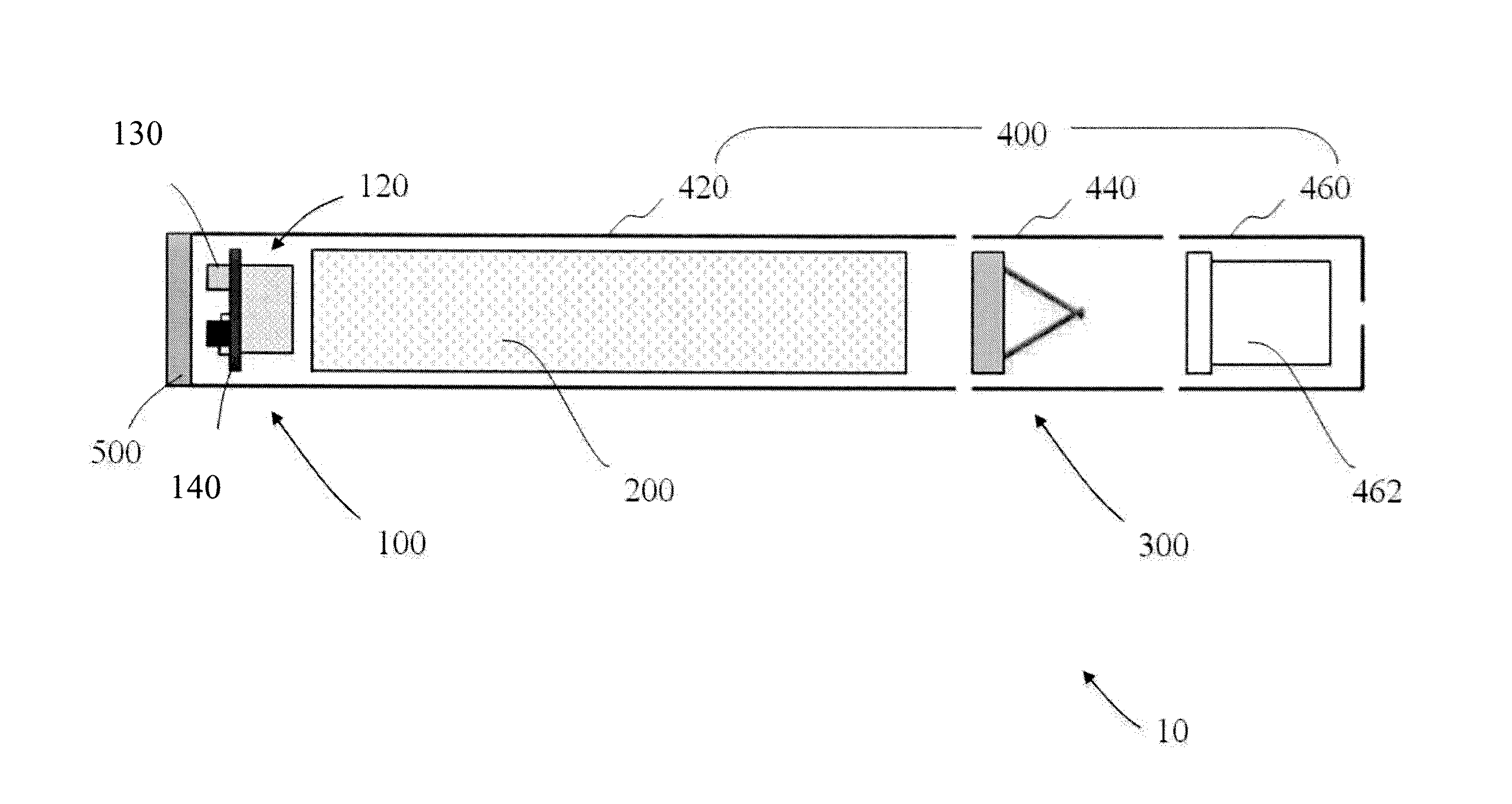
[0026]The electronic cigarette (10) as an example of an electronic smoke as shown in FIG. 8 comprises an inhale detector (100) as an example of an air-flow rate and direction detector, a battery (200) as an example of stored power source, a nicotine source as a example of a smoke or favor (or aroma) source, and a heating element (300) as a heating means. The inhale detector, the battery and the heating element are all housed within a main housing (400) which comprises a first tubular portion (420) in which the battery and the inhale detector are mounted, a second tubular portion (440) in which the heating element and the nicotine source are mounted, and a third tubular portion (460) containing a mouth piece (462). In addition, a transparent or translucent cover (500) is attached to the downstream end of the first tubular portion.

[0027]The inhale detector is a modular assembly comprising an air-flow sensor (120), an actuation circuit and an LED light source (130), which are all mount...


PUM


Abstract

An electronic smoke comprising an inhale detector and a smoke effect generating circuitry. The inhale detector comprises an air-flow sensor which is arranged to detect direction and rate of air flow through the smoke apparatus, and the smoke effect generating circuitry is arranged to operate the smoke effect generating circuitry to generate smoking effect when the air flow direction corresponds to inhaling through the apparatus and the air flow rate reaches at predetermined threshold. Such an electronic smoke alleviates the problem of inadvertent triggering due to environmental vibration or noise or children playing by blowing into the device.

Description

FIELD OF THE INVENTION[0001]The present invention relates to electronic smoke apparatus (or electronic smoke in short), and more particularly to electronic cigarettes. The present invention also relates to air-flow rate and direction detector for use in an electronic smoke apparatus.BACKGROUND OF THE INVENTION[0002]Electronic smoke apparatus such as electronic cigarettes provide a smoking alternative to smokers. An electronic smoke is a non-naked flame smoking apparatus which typically comprises a battery powered heater arranged to vaporize liquid nicotine or nicotine substitutes upon actuation by a user. The heater is usually automatically actuated by a controller when a user inhales through the electronic smoke to simulate a smoking action. Typically, an inhaling detector is provided in an electronic smoke and the controller, such as a digital signal processor (DSP) will actuate the heater when inhaling is detected by the inhaling detector. An exemplary equivalent application circ...

Claims


Application Information

Patent Timeline
IPC IPC(8): A24F47/00G01F1/56A24F40/485A24F40/51
CPCA24F47/008G01F1/28G01P13/0033G01P13/0026A24F40/51A24F40/485
Inventor LIU, LOI YING
Owner AKRIA CLIENT SERVICES LLC
Learn More