

Terminal block and terminal block manufacturing method
a technology of terminal blocks and manufacturing methods, which is applied in the direction of electrical cable installation, electrically conductive connections, bus-bar installation, etc., can solve the problems of not being able to mount nuts on positioning pins, no means for positioning heat sinks, and no means for positioning nuts at predetermined positions, so as to improve an insulating property and long creepage distance
- Summary
- Abstract
- Description
- Claims
- Application Information
AI Technical Summary
Benefits of technology
Problems solved by technology
Method used
Image

Examples
Embodiment Construction
[0039]A terminal block in accordance with the invention is to be mounted in a motor case to be installed in a vehicle such as an electric vehicle or a hybrid vehicle and is provided to electrically connect a busbar of a first electric equipment such as an electric motor (e.g. a three-pole busbar provided in a three-phase alternating current motor) and a busbar of a second electric equipment such as an inverter (e.g. a three-pole busbar provided in an inverter).
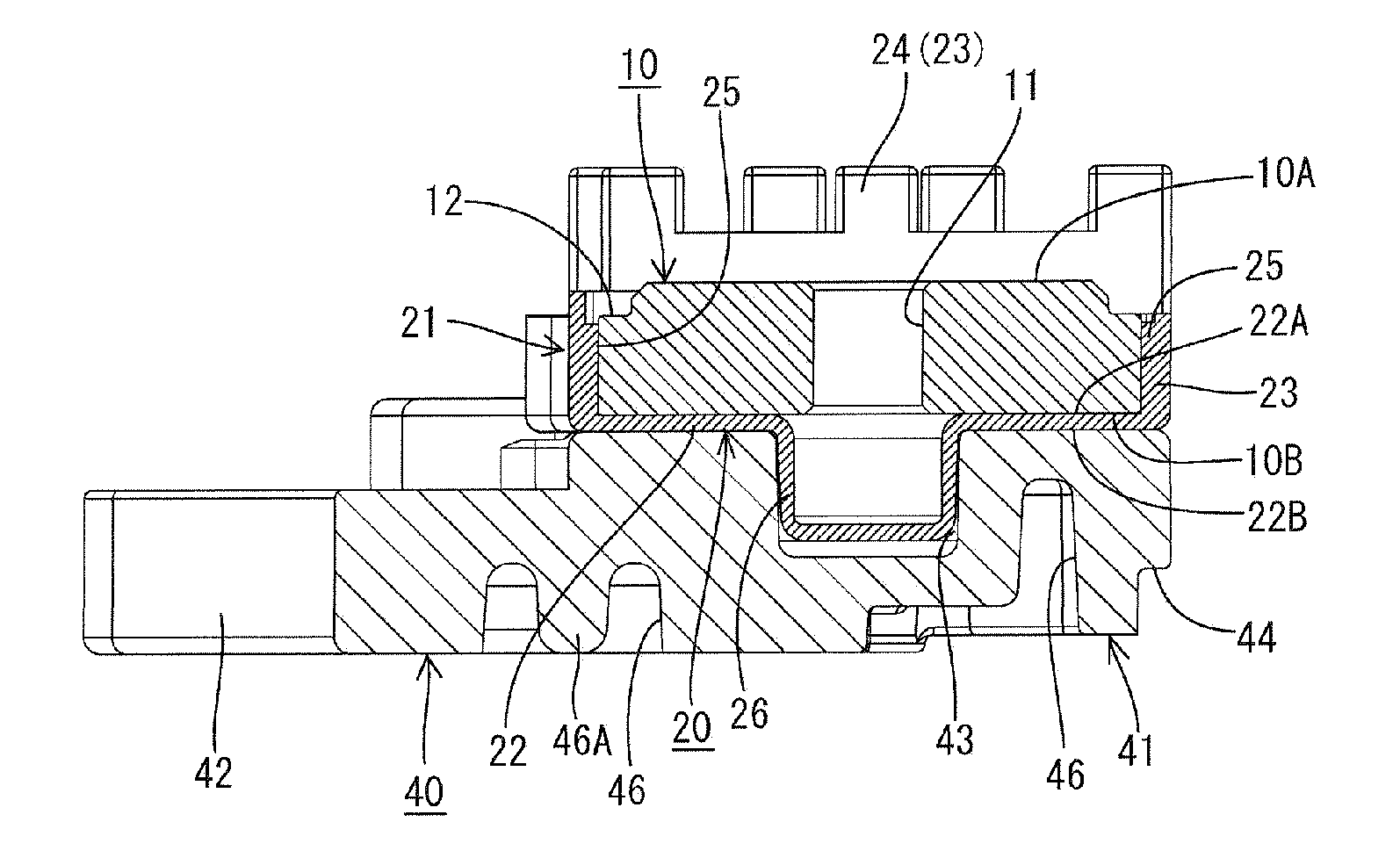
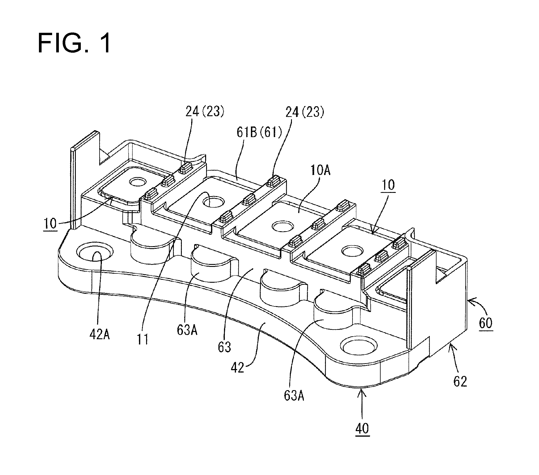
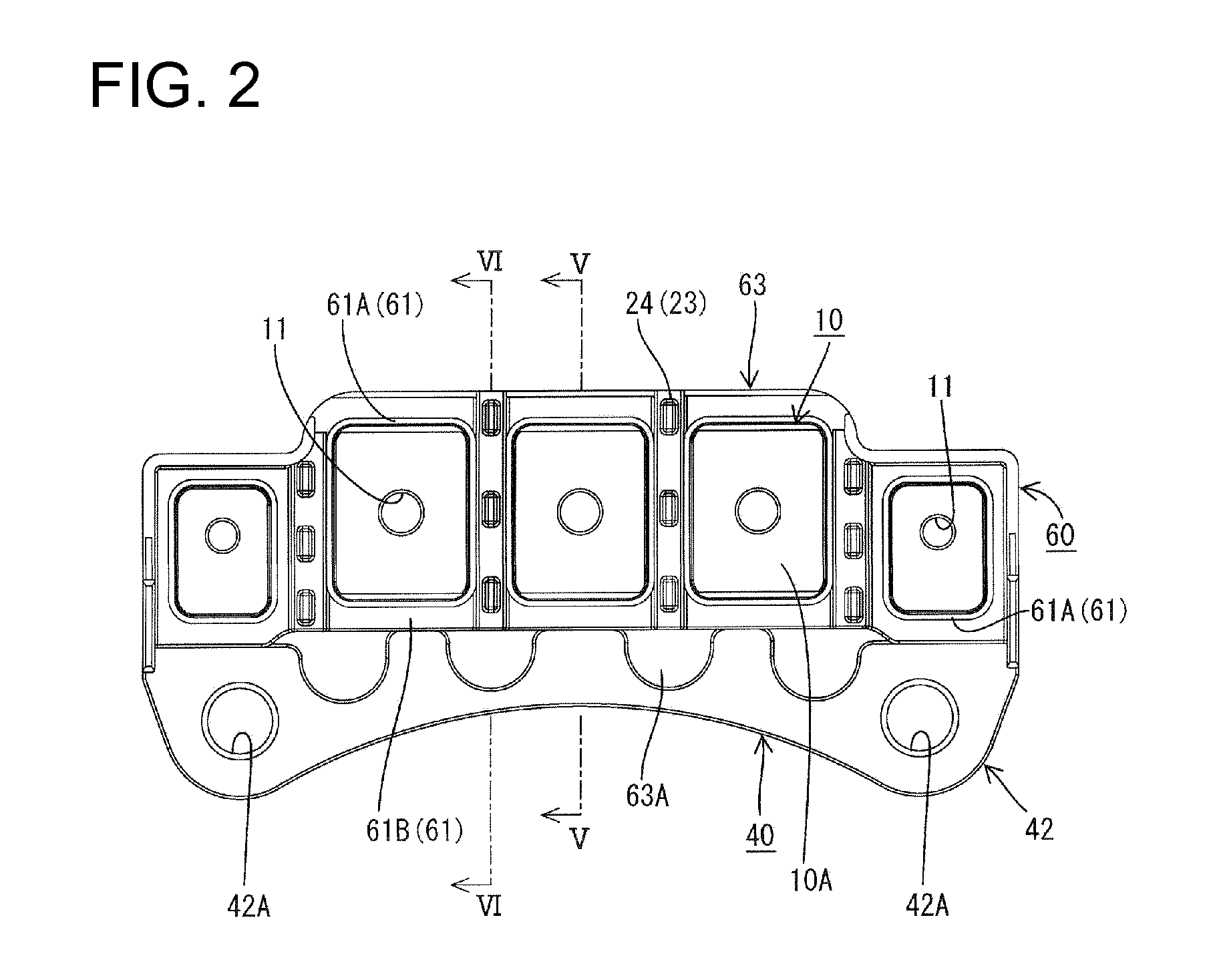
[0040]The terminal block includes nuts 10 with upper and lower surfaces. Unillustrated busbars extending from electrical devices are to be placed on the upper surfaces of the nuts 10 and a heat sink 40 is arranged adjacent to the lower surfaces of the nuts 10. An insulating plate 20 is sandwiched between the nuts 10 and the heat sink 40. A molded resin part 60 made e.g. of synthetic resin at least partly covers the nuts 10, the insulating plate 20 and the heat sink 40. In the following description, a vertical direction is base...
PUM
| Property | Measurement | Unit |
|---|---|---|
| Time | aaaaa | aaaaa |
| Current | aaaaa | aaaaa |
| Current | aaaaa | aaaaa |
Abstract
Description
Claims
Application Information