
Detachable umbrella, walking stick/cane, crutch holder for use on mobility vehicle such as but not limited to electric scooters, electric wheelchairs, wheelchairs and walkers

a technology for mobility vehicles and umbrellas, which is applied to washstands, scaffold accessories, and lighting supports. it can solve the problems of clumsy, uncomfortable or dangerous holding of items by hand or between users' legs, and the conventional method of tying items to vehicles or using bungee cords is clumsy and/or time-consuming or ineffective, and the device has a tendency to swing or rock from side to side, so as to facilitate folding, storage, and movemen

Inactive Publication Date: 2012-07-26
BAKERMAN MARTIN ROY
View PDF7 Cites 9 Cited by
  • Summary
  • Abstract
  • Description
  • Claims
  • Application Information

AI Technical Summary

Benefits of technology

[0030]The present invention is directed toward a holder that easily attaches and detaches to an electric scooter, electric wheelchair, manual wheelchair, walker, or other similar device, to temporarily secure, attach, hold or carry any object that contains at least one or more legs, tips or ends, such as, but not limited to an umbrella, a walking stick, a walking cane, a crutch or other item. The device, object of the present invention, is easily attached or removed from the mobility unit by means of two hanger prongs which fit into or slide into two hanger brackets which are attached to the mobility device either in a permanent fashion by the use of glue or screws or any other way to permanently affix them or they may be attached in a way that facilitates their removal by the use of one of the countless clamps or connectors that are readily available in the market place.
[0034]Still another object of the present invention is to provide a method of attaching said object of the present invention to its host mobility vehicle facing any direction that is preferred in order to make use of the object of the present invention more effectively or comfortably. The object of the present invention may be attached on a square, round or rectangular tube that is angled anywhere from the midpoint between horizontal and vertical to completely vertical or upright and could be facing forward, backward, inward or outward in relation to the mobility vehicle, where the vehicle's design allows it to be placed so that it may be utilized in a workable manner.
[0036]Still another object of the present invention is to provide a method of a simple way to remove both the object of the present invention and the item that is being held or carried by the present invention simultaneously while the item being held or carried is still attached to the present invention. While remaining so attached they may also be simultaneously simply and easily re-installed on the vehicle from which they were removed.
[0037]A further object of the present invention is the ability of easily removing and re-installing the object of the present invention in order to facilitate folding, storing, moving, or any other reason where the object of the present invention still attached is of an issue, such as the overall height of the vehicle.
[0038]Another object of the present invention is the ability of being used without disabling or making useless any of the design and function elements of the vehicle on which it is being used.

Problems solved by technology

It is difficult, clumsy, uncomfortable or dangerous to hold them by hand or between the user's legs or to balance them precariously on the floor of the mobility vehicle while operating the mobility vehicle.
Most conventional methods of securing these items by means of tying them on to the vehicle or using bungee cords to secure them are clumsy and / or time consuming or ineffective.
Still furthermore the item being carried or secured by Cumins, device will have a tendency to sway or rock from side to side as it is being held at only one point and that point being on one of the extreme ends of the item being carried.
Crysor and Hutchinson prior art devices are attached toward the top of the item being carried and therefore the item being carried will hang in a vertical manner and will not allow it to be carried in any near vertical but not vertical manner.
Still furthermore the item being carried or secured by Crusor and / or Hutchinson device will have a tendency to sway or rock from side to side as it is being held at only one point and that point being on one of the extreme ends of the item being carried.
All prior art devices do not offset the item being carried which allows normal functions on the mobility devices to operate in a way that they were designed, in example, the arms would not be able to be raised.

Method used


Image

  • Detachable umbrella, walking stick/cane, crutch holder for use on mobility vehicle such as but not limited to electric scooters, electric wheelchairs, wheelchairs and walkers
  • Detachable umbrella, walking stick/cane, crutch holder for use on mobility vehicle such as but not limited to electric scooters, electric wheelchairs, wheelchairs and walkers
  • Detachable umbrella, walking stick/cane, crutch holder for use on mobility vehicle such as but not limited to electric scooters, electric wheelchairs, wheelchairs and walkers

Examples


Embodiment Construction

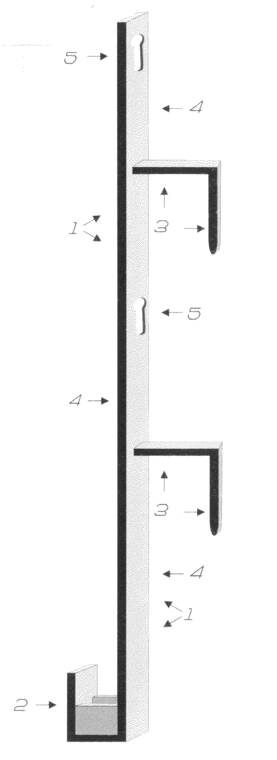
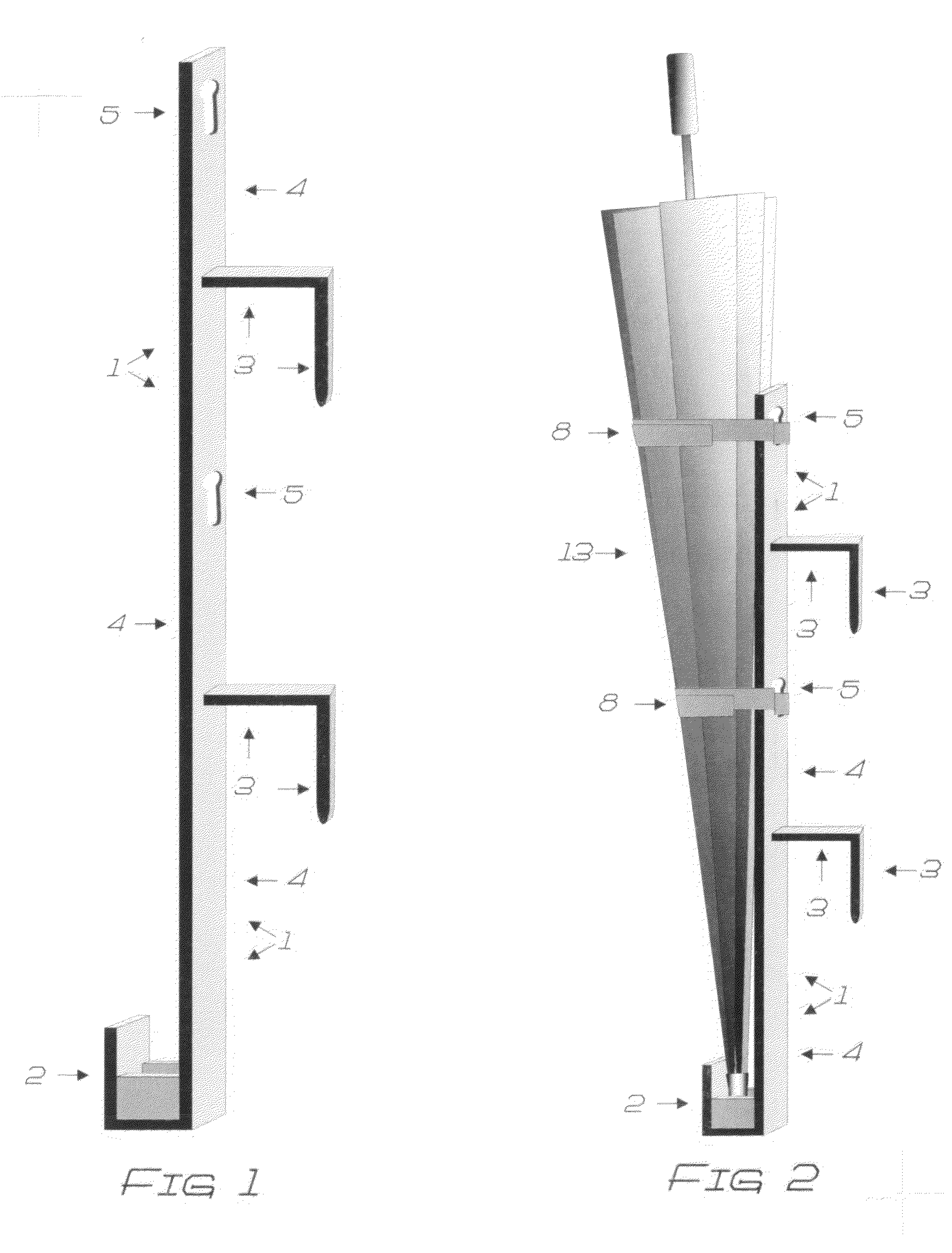
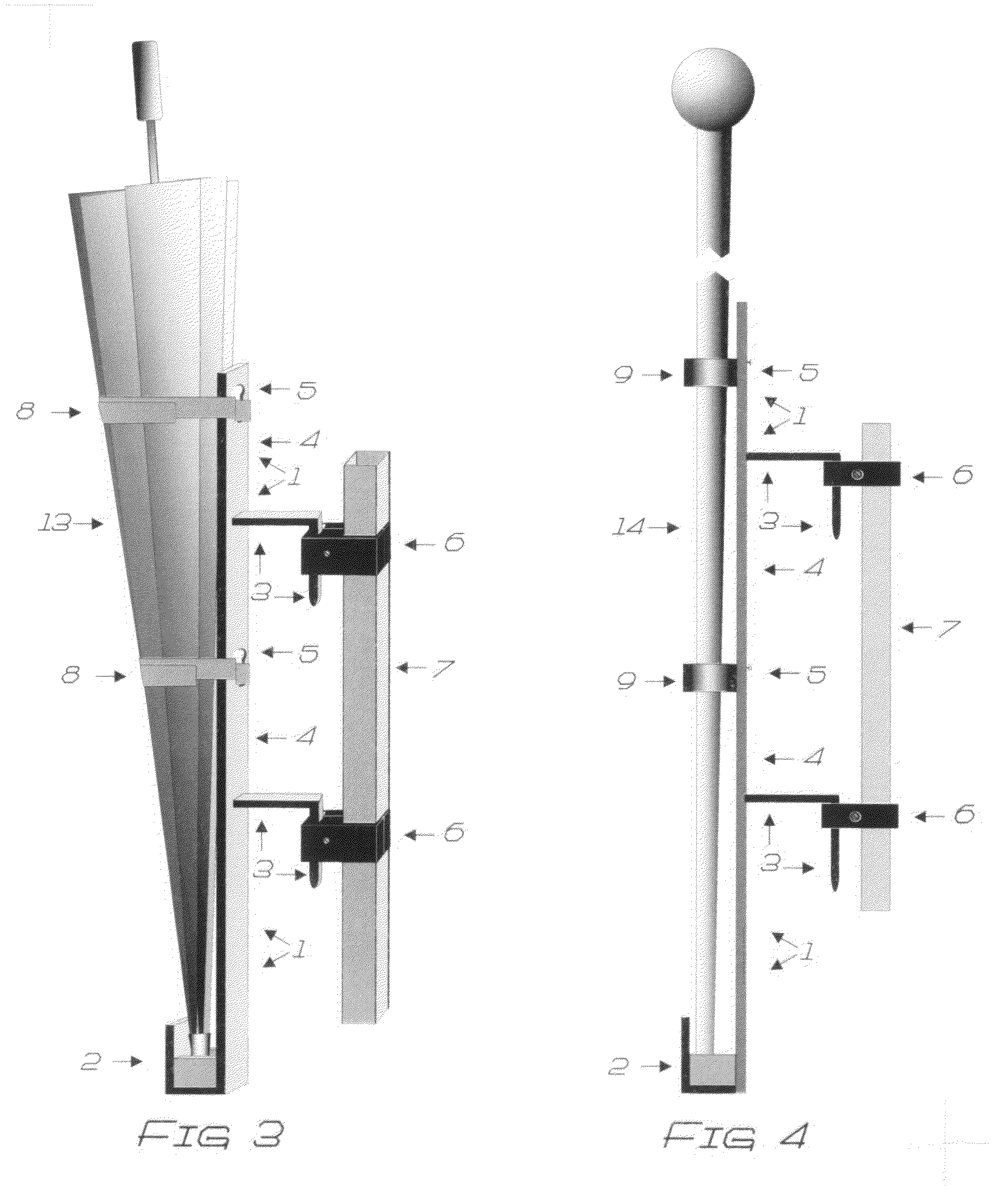
[0050]Shown throughout FIGS. 1-8, the present invention is directed toward an attachable / detachable device that is used to hold any object that contains at least one or more legs, tips or ends. Specifically, the detachable holder, object of the present invention 1 (see FIG. 1), is to be utilized on a mobility unit to temporarily hold or secure an item the user does not wish to carry or hold in their hands at that given moment. As shown in the figures, the item being held or secured can be an umbrella 13 (see FIG. 2&FIG. 3), a walking stick 14 (see FIG. 4), a walking cane 15 (see FIG. 5), a crutch 16 (see FIG. 6), These embodiments, however are only illustrative of the numerous types of items for which this attachable / detachable holding devise, the object of the present invention could be effectively utilized. In fact any item which presently exists or is developed that has an edge, end or tip that fit into the support 2 or into the insert extender for larger bases or tips 12 (see FI...


PUM


Abstract

A device that easily attaches and detaches to brackets which have been attached to a tube be it round, square, or rectangle, found on a mobility unit such as but not limited to an electric scooter, electric wheelchair, manual wheelchair, walker, or other similar vehicle, to temporarily secure, attach, or hold any object that contains at least one or more legs, tips or ends, such as an umbrella, a walking stick, a walking cane, a crutch or other item. The tube to which the device is attached may be vertical or angled as much as halfway between vertical and horizontal. The device is easily removable from the mobility unit, with or without the object that it is being used to secure, attach, or hold, still attached, secured, or held, in order to facilitate folding, storing, or transporting the mobility unit.

Description

CROSS-REFERENCE TO RELATED APPLICATIONS[0001]Title: Umbrella Holder[0002]Inventor: Thomas B. Comins[0003]U.S. Pat. No.: 494,123[0004]Filing Date: Jul. 18, 1892[0005]Issue Date: Mar. 18, 1893[0006]Title: Walking Cane Holder Apparatus[0007]Inventor: Jack M Hutchinson, et al[0008]U.S. Pat. No.: 6,691,722[0009]Filing Date: Jun. 19, 2002[0010]Issue Date: Feb. 17, 2004[0011]Title: Cane Holding Apparatus and Method[0012]Inventor: Jackie B Crysor[0013]U.S. Pat. No.: 6,000,414[0014]Filing Date: Dec. 11, 1997[0015]Issue Date: Dec. 14, 1999[0016]Title: Multipurpose Carrying System[0017]Inventor: Giancarlo Caputi[0018]Application Ser. No.: 91,794,071[0019]Filing Date: Feb. 28, 2001[0020]Publication Number: US 2002 / 0008125A1BACKGROUND OF THE INVENTION[0021]A. Field of the Invention[0022]The present invention relates to a device that easily attaches and detaches to any vertical or nearly vertical upright tube to hold or secure for a temporary time an item such as, but not limited to an umbrella, ...

Claims


Application Information

Patent Timeline
Patent Type & Authority Applications(United States)
IPC IPC(8): F16M13/02
CPCA61H3/0244B60R7/12A61H2003/0255A61H2003/003A61H2003/002
Inventor BAKERMAN, MARTIN ROY
Owner BAKERMAN MARTIN ROY
Learn More