Backlight lamp cover, backlight backboard and liquid crystal display module

a liquid crystal display module and backlight technology, applied in non-linear optics, instruments, optics, etc., can solve the problems of low efficiency of assembling the backlight, large proportion of the cost of the entire liquid crystal display, and low development cost of dies, so as to improve the structure of the lamp cover and dissipate heat. , the effect of improving the structure of the backboard

Inactive Publication Date: 2012-07-26
BOE TECH GRP CO LTD
View PDF5 Cites 8 Cited by
  • Summary
  • Abstract
  • Description
  • Claims
  • Application Information

AI Technical Summary

Benefits of technology

[0012]Embodiments of the present disclosure provide a backlight lamp cover, a backlight backboard and a liquid crystal display module. According to embodiments of the present disclosure, the structure of the lamp cover is improved in that besides the functions of protecting a lamp tube and dissipating heat from the lamp tube, the backlight lamp cover is further provided with a bending structure to support and limit a movement of the liquid crystal display panel as well as to support a bezel, so that the lamp cover provides main functions of a mold frame in the related art in substitution of the latter. In consideration of that the backlight lamp cover is only accommodated in the backlight backboard at the side portion corresponding to the light incident surface of the light guide plate, and side portions of the backlight backboard not for accommodating the backlight lamp cover do not completely limit the movement of the

Problems solved by technology

In a liquid crystal display, a backlight is an important component, for providing a light source for a liquid crystal display in work, and the backlight constitutes a large proportion of a cost of the entire liquid crystal display.
The inventor finds that the related art has at least the

Method used


Image

  • Backlight lamp cover, backlight backboard and liquid crystal display module
  • Backlight lamp cover, backlight backboard and liquid crystal display module
  • Backlight lamp cover, backlight backboard and liquid crystal display module

Examples


first embodiment

The First Embodiment

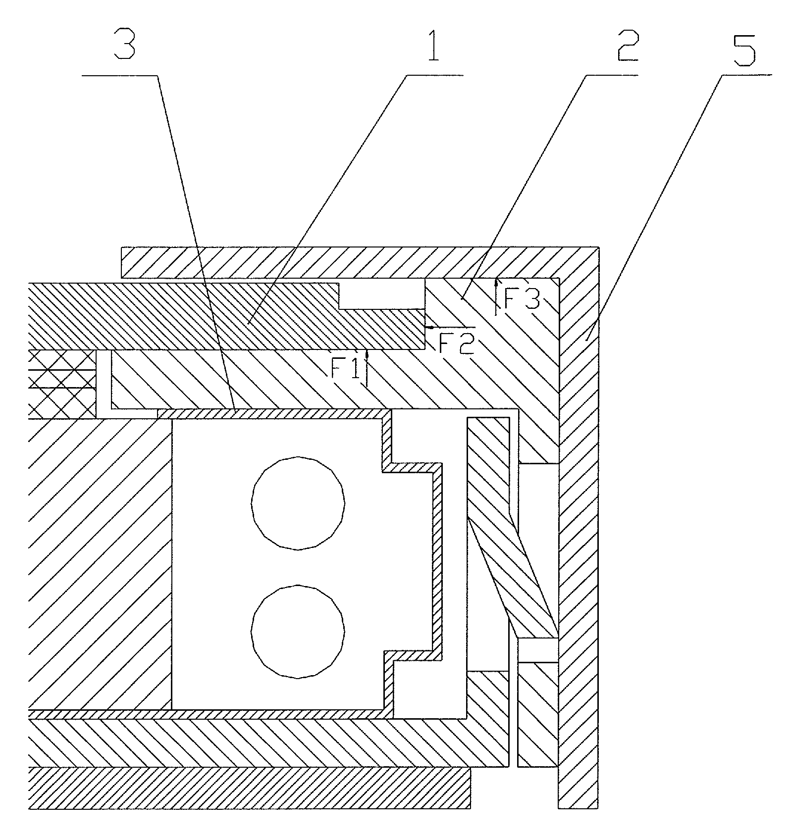
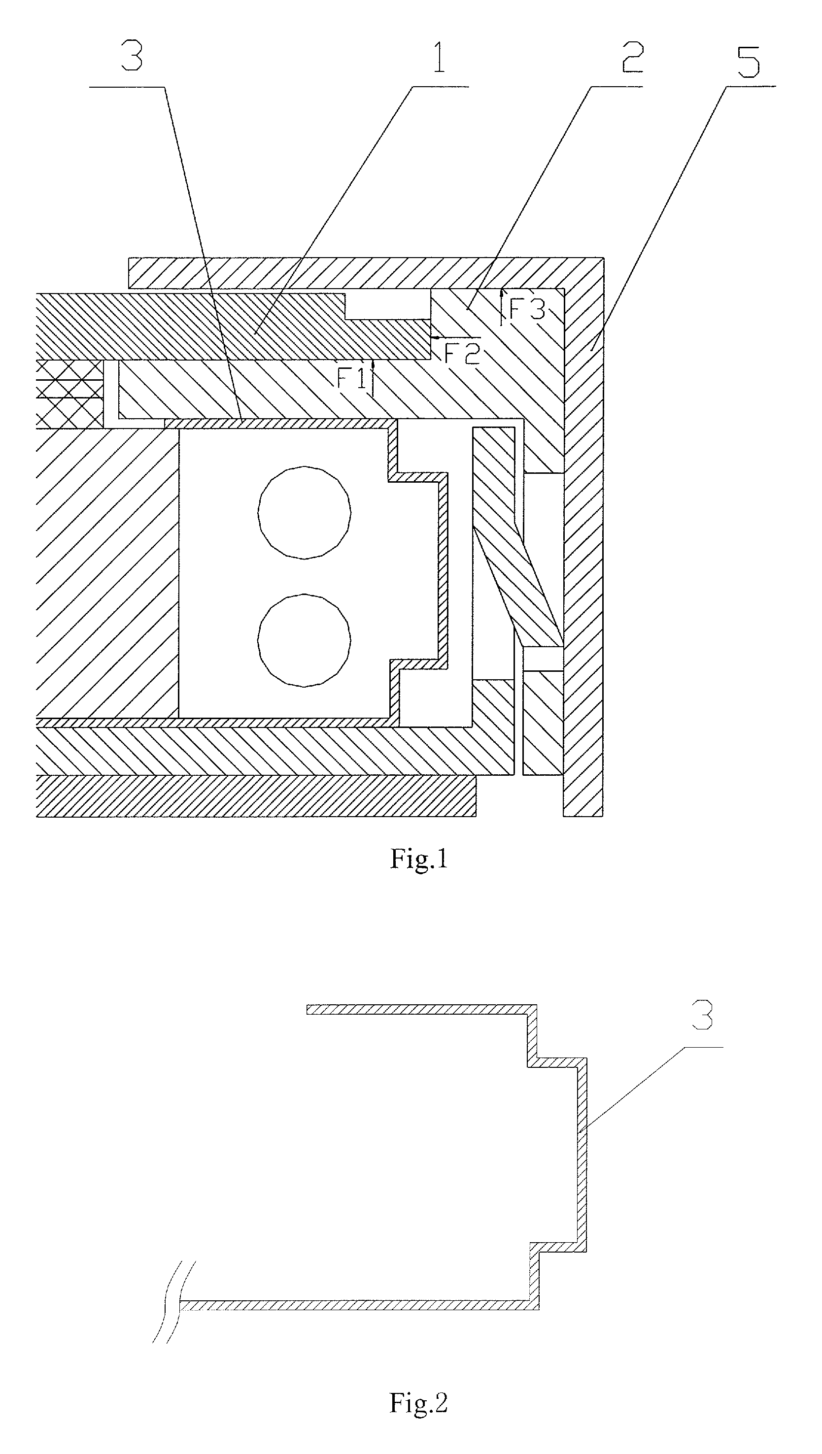
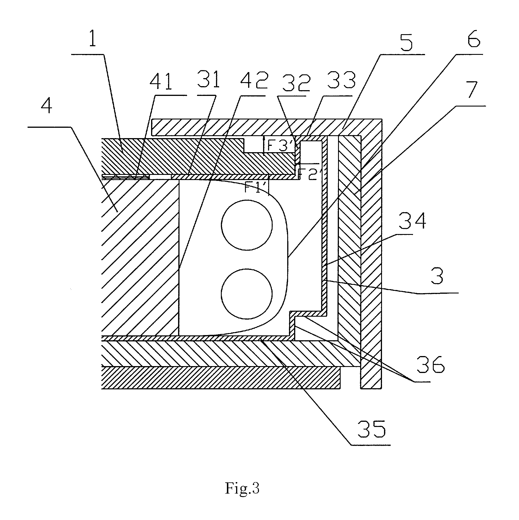
[0021]This embodiment provides a backlight lamp cover. As shown in FIG. 3 and FIG. 4, besides the functions of protecting a lamp tube and dissipating heat from the lamp tube, the backlight lamp cover 3 further comprises a supporting plate 31, which is mounted at a light emitting surface side of a light guide plate 4 and directly supports a liquid crystal display panel 1, with the supporting force for supporting the liquid crystal display panel illustrated as F1′ in FIG. 3. Moreover, a bending structure is added on an edge of the supporting plate 31. A first turning portion 32 of the bending structure is bent upward in FIG. 3 so as to limit a movement of the liquid crystal display panel 2 on the supporting plate 31 by means of the first turning portion 32. The acting force of the first turning portion 32 for limiting the movement of the liquid crystal display panel 1 is illustrated as F2′ in FIG. 3. The bending structure also comprises a second turning portion 33 ...

second embodiment

The Second Embodiment

[0026]The present embodiment provides a backlight backboard. As shown in FIG. 3 and FIG. 7, the backboard 7 is used for mounting a backlight lamp cover 3. However, the backlight lamp cover 3 is only accommodated at the side portion of the backlight backboard 7 corresponding to the light incident surface of the light guide plate 4, whereas the side portions of the backlight backboard 7 not accommodating the backlight lamp cover 3 do not completely limit the position of the liquid crystal display panel 1 In consideration of the above situation, the structure of the backlight backboard 7 is also improved correspondingly, so that the backlight backboard 7 comprises a stepped structure located at the top end of a side portion thereof not accommodating the backlight lamp cover 3. The stepped structure comprises a supporting portion 71 for supporting the liquid crystal display panel 1 and a stopper portion 72 for limiting a movement of the liquid crystal display panel ...

third embodiment

The Third Embodiment

[0029]The present embodiment provides a liquid crystal display module, which, as shown in FIG. 3 and FIG. 7, comprises a light guide plate 4, a liquid crystal display panel 1 and a bezel 5. The module further comprises: a backlight lamp cover 3, which comprises a supporting plate 31 located at a light emitting surface side of a light guide plate for supporting the liquid crystal display panel 1 and having at an edge thereof a bending structure that comprises a first turning portion 32 for limiting a movement of the liquid crystal display panel on the supporting plate 31 and a second turning portion 33 for supporting the bezel 5; and a backlight backboard 7, of which the side portion corresponding to the light incident surface of the light guide plate 4 is used for accommodating the backlight lamp cover 3, and the side portions not accommodating the backlight lamp cover 3 are provided at the top end thereof with a stepped structure that comprises a supporting port...


PUM


Abstract

The present disclosure provides a backlight lamp cover, a backlight backboard and a liquid crystal display module. According to the present disclosure, a lamp cover is improved by further providing a bending structure to support and limit a movement of a liquid crystal display panel as well as to support a bezel, in substitution of main functions of a mold frame in the related art. At the same time, the backboard structure is improved accordingly by adding a stepped structure so as to supplementally limit the liquid crystal display panel. Thus, the functions of a mold frame in the related art can be provided without a conventional mold frame in a liquid crystal display module. That is, one part is reduced.

Description

FIELD OF THE INVENTION[0001]Embodiments of the present disclosure relate to a display apparatus, and in particular to a backlight lamp cover, a backlight backboard and a liquid crystal display module.BACKGROUND OF THE INVENTION[0002]A Thin Film Transistor Liquid Crystal Display (TFT-LCD) has advantages such as small volume, low power consumption, no radiation, etc., and occupies the leading position of the flat panel display market, being widely used in various fields such as liquid crystal televisions, computers, cell phones, PDA, and so on. In a liquid crystal display, a backlight is an important component, for providing a light source for a liquid crystal display in work, and the backlight constitutes a large proportion of a cost of the entire liquid crystal display. Therefore, reduction in the cost of the backlight becomes one of the aims in continuous competitions of every manufacturing factory.[0003]As shown in FIG. 1, a typical liquid crystal display module comprises a backli...

Claims


Application Information

Patent Timeline
IPC IPC(8): G02F1/1333
CPCG02F1/133615G02F1/133308
Inventor HAN, RUI
Owner BOE TECH GRP CO LTD
Why Eureka
Try Eureka