Device for optically scanning and measuring an environment

a technology for optical scanning and measuring an environment, applied in measurement devices, active open surveying means, instruments, etc., can solve problems such as methods failing in closed halls, and achieve the effect of identifying and moving relatively easily

Active Publication Date: 2012-07-26
FARO TECH INC
View PDF13 Cites 49 Cited by
  • Summary
  • Abstract
  • Description
  • Claims
  • Application Information

AI Technical Summary

Benefits of technology

[0005]The position of the laser scanner is changed between the scans. In place of the path followed by the laser scanner from the old center to the new center, the path of a reference point of the laser scanner, for example of a base, which reference point is stationary with regard to the scanning process, can be considered. The device according to embodiments of the invention makes it possible to trace, at least approximately, this path, i.e. the difference vector between the old center and the new center. The scans made for this purpose can then be joined together (registered) more easily, since the targets contained in the scans, the positions of which targets can be estimated well when knowing the path followed, can be localized and identified more easily. Knowledge of the approximate position is sufficient, since, by image processing, deviations can be corrected, up to a certain value. The path is traced by an optical measuring device, wherei

Problems solved by technology

It is a problem that this m

Method used


Image

  • Device for optically scanning and measuring an environment
  • Device for optically scanning and measuring an environment
  • Device for optically scanning and measuring an environment

Examples


Embodiment Construction

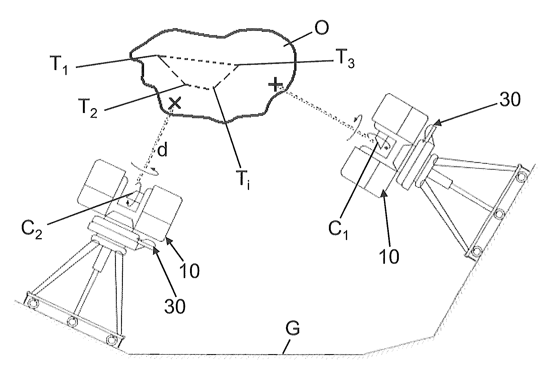
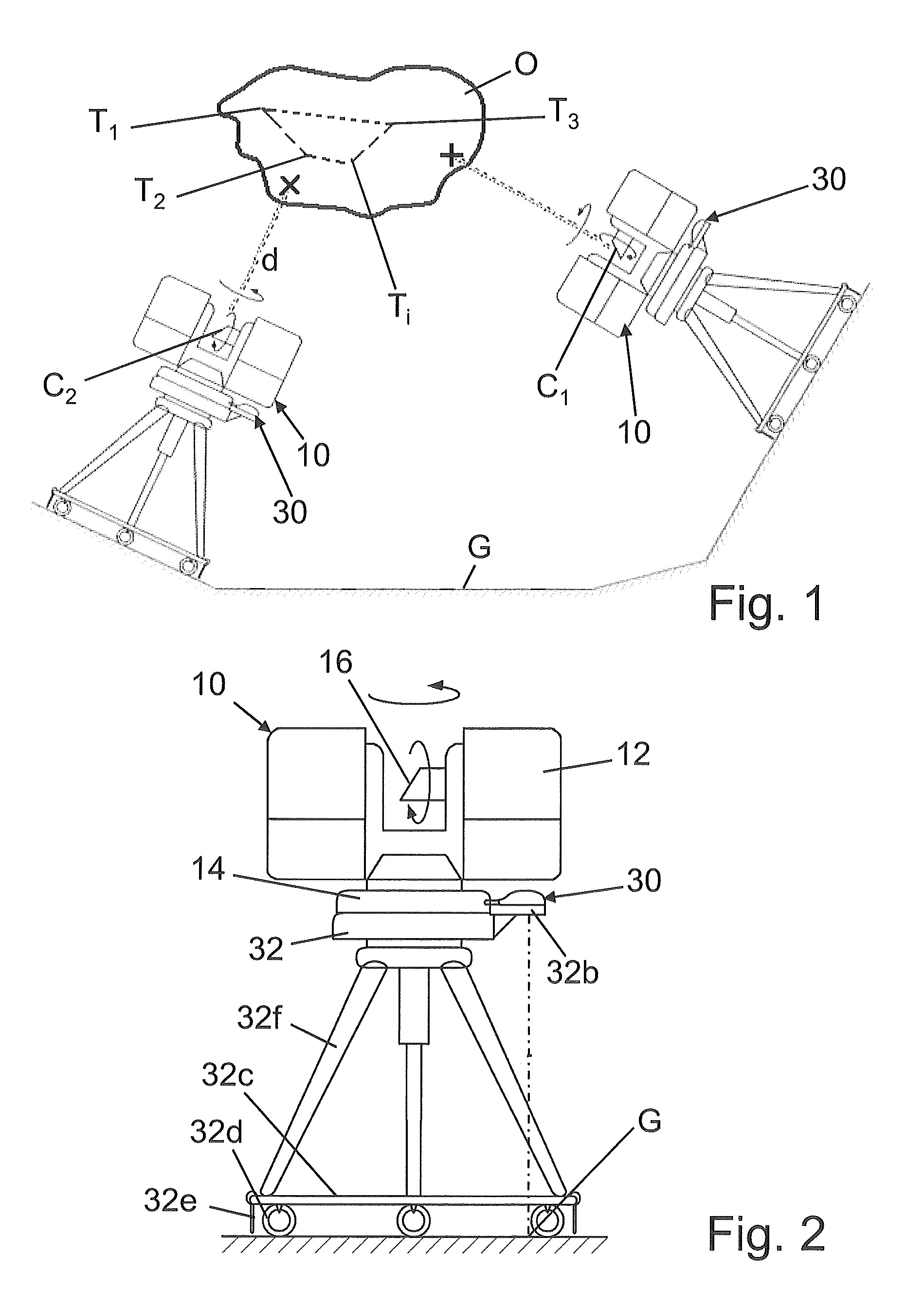
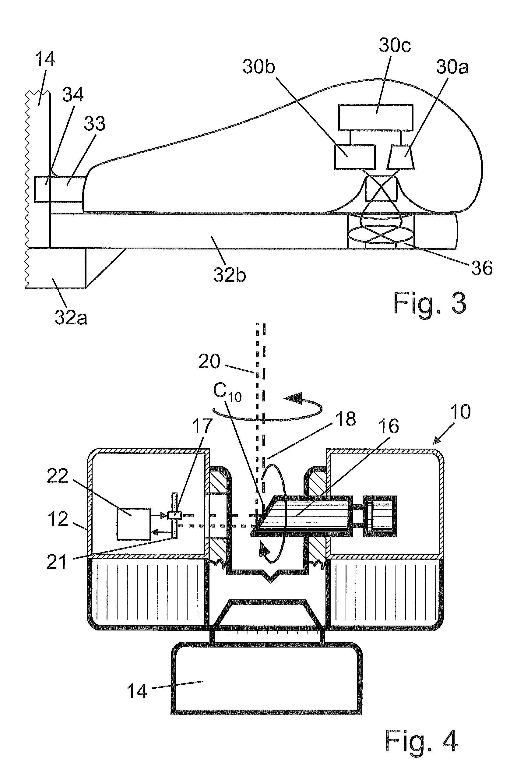
[0016]Referring to FIGS. 2 and 4, a laser scanner 10 is provided as a device for optically scanning and measuring the environment of the laser scanner 10. The laser scanner 10 has a measuring head 12 and a base 14. The measuring head 12 is mounted on the base 14 as a unit that can be rotated about a vertical axis. The measuring head 12 has a mirror 16, which can be rotated about a horizontal axis. The intersection point of the two rotational axes is designated as the center C10 of the laser scanner 10.

[0017]Referring to FIG. 4, the measuring head 12 is further provided with a light emitter 17 for emitting an emission light beam 18. The emission light beam 18 may be a laser beam in the visible range of approximately 340 to 1600 nm wave length, for example 790 nm; however, other electro-magnetic waves having, for example, a greater wave length can be used. The emission light beam 18 is amplitude-modulated, for example with a sinusoidal or with a rectangular-waveform modulation signal....


PUM


Abstract

In a laser scanner for optically scanning and measuring an environment, the scanner having a center which defines for a scan the stationary reference system of the scanner and the center of the scan, a light emitter which emits an emission light beam, a light receiver which receives a reception light beam reflected by an object in the environment of the scanner, a control and evaluation unit which determines, for a multitude of measuring points of the scan, at least the distance between the center of the scan and the object, the scanner, for registering a scene with several scans having different centers, being movable between the centers of the scans, and a scanner mouse for registering the path followed by the scanner between the different centers of the scans, the scanner mouse optically registering the movement of the laser scanner relative to a reference surface.

Description

CROSS-REFERENCE TO RELATED APPLICATIONS[0001]The present application is a National Stage Application of PCT Application No. PCT / IB2010 / 002226 filed on Jul. 20, 2010, which claims the benefit of U.S. Provisional Patent Application No. 61 / 299,545 filed on Jan. 29, 2010, and of pending German Patent Application No. DE 10 2009 035 336.4, filed on Jul. 22, 2009, and which are hereby incorporated by reference.BACKGROUND OF THE INVENTION[0002]The invention relates to a device for optically scanning and measuring an environment.[0003]By a device such as is known for example from U.S. Published Patent Application No. 2010 / 0134596, and which is designed as a laser scanner, the environment of the laser scanner can be optically scanned and measured. If a scene shall be taken by several scans which are joined together by different targets, the center of the corresponding scan can be approximately determined by a Global Positioning System (GPS), so that the targets in the scans can be clearly loc...

Claims


Application Information

Patent Timeline
IPC IPC(8): G01B11/24G01S17/89
CPCG01C15/002G01S7/003G01S17/89G01S17/42G01S17/50G01S7/4811
Inventor BECKER, REINHARDOSSIG, MARTIN
Owner FARO TECH INC
Why Eureka
Try Eureka