Tire condition detecting device

a technology for detecting devices and tires, applied in the direction of electrical apparatus casings/cabinets/drawers, instruments, transportation and packaging, etc., can solve the problems of deterioration of sealants, deformation, and disruption of the adhesive interface between, so as to prevent the breakdown of electronic components

Active Publication Date: 2012-07-26
BRIDGESTONE CORP
View PDF4 Cites 6 Cited by
  • Summary
  • Abstract
  • Description
  • Claims
  • Application Information

AI Technical Summary

Benefits of technology

[0008]Accordingly, an object of the present invention is to provide a tire condition detecting device capable of surely detecting tire conditions such as inner pressure and temperature of a tire and preventing a breakdown of an electronic component even in an environment where water content such as a coolant is injected in the tire.
[0010]According to such an aspect, the inside of the box unit having the opening surface covered by the lid unit is filled with the sealant. Thereby, in an environment inside the tire in which water content such as a coolant is injected, even when the tire condition detecting device is completely immersed, the sealant is never directly immersed in the water content. This retards progress in the deterioration of the sealant. Accordingly, the sealant can be prevented from deforming, and a disruption of the adhesive interface between the sealant and the casing can be surely prevented. Thus, a breakdown of the electronic component is prevented, and the tire conditions such as inner pressure and temperature of the tire can be surely detected.
[0014]The aspects of the present invention can provide a tire condition detecting device capable of surely detecting tire conditions such as inner pressure and temperature of a tire and, preventing a breakdown of an electronic component even in an environment where water content such as a coolant is injected in the tire.

Problems solved by technology

However, the conventional tire condition detecting device described above has the following problems.
In such a case, the deterioration of the sealant is likely to progress.
Thereby, the sealant 370 is deformed, disrupting the adhesive interface between the sealant and the casing.
This results in a problem that the tire conditions such as inner pressure and temperature of the tire cannot be detected.

Method used


Image

  • Tire condition detecting device
  • Tire condition detecting device
  • Tire condition detecting device

Examples


modification example

(4) MODIFICATION EXAMPLE

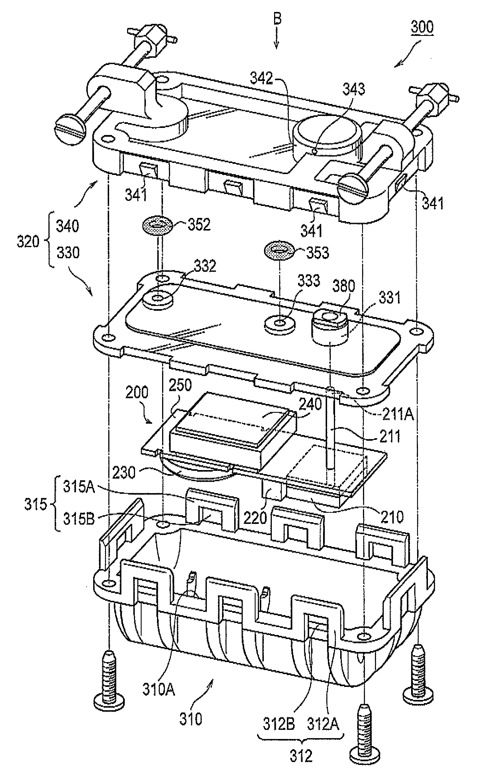
[0059]Next, Modification Example of the tire condition detecting device 100 according to the above-described embodiment will be described by referring to a drawing. FIG. 6 is a cross-sectional view showing a part of a tire condition detecting device 100A according to Modification Example. Note that the same reference signs denote same elements and portions as those of the tire condition detecting device 100 according to the above-described embodiment, and different elements and portions will be mainly described.

[0060]In the above-described embodiment, the pipe insertion hole 331, the injection hole 332 and the discharge hole 333 are formed in the middle plate 330. In addition, the recessed portion 342 is formed in the outer cover 340 in the embodiment.

[0061]In contrast, in Modification Example, as shown in FIG. 6(a), the pipe insertion hole 331, the injection hole 832, and the discharge hole 333 are formed in the casing main body 310. The O-ring 351, the O-ri...


PUM


Abstract

A tire condition detecting device according to the present invention includes: an electronic component including a sensor configured to detect a tire condition; and a casing configured to house the electronic component. The casing includes a casing main body configured to house the electronic component and having an opening surface formed thereon, and a lid unit configured to cover the opening surface. An inside of the casing main body having the opening surface covered by the lid unit is filled with a sealant. Accordingly, tire conditions such as inner pressure and temperature of a tire can be surely detected and a breakdown of an electronic component can be prevented even in an environment where water content such as a coolant is injected in the tire.

Description

TECHNICAL FIELD[0001]The present invention relates to a tire condition detecting device having an electronic component including a detector configured to detect tire conditions such as inner pressure and temperature of a tire.BACKGROUND ART[0002]Heretofore, for a tire condition detecting device configured to detect tire conditions such as inner pressure and temperature of a tire, the following structure has been widely adopted. Specifically, electronic components such as a transmitter and a pressure-temperature sensor are mounted on a circuit board which is housed in a casing (box unit) made from a synthetic resin.[0003]For such a tire condition detecting device, a method is known in which the circuit board housed in the casing having an opening surface formed thereon is sealed with a sealant such as an epoxy based resin (for example, Patent Document 1). Sealing the circuit board housed in the casing with the sealant can suppress a breakdown of the tire condition detecting device, w...

Claims


Application Information

Patent Timeline
Patent Type & Authority Applications(United States)
IPC IPC(8): H05K7/00
CPCB60C23/0493
Inventor YAMAGUCHI, SHIGERU
Owner BRIDGESTONE CORP
Why Eureka
Try Eureka