Ring light illuminator, beam shaper and method for illumination

a technology of ring light and beam shaper, which is applied in the direction of lighting support devices, lighting and heating apparatus, instruments, etc., can solve the problems of large divergence of light exiting an optical fibre, inability to achieve the degree of homogeneity of illumination field required for some applications, and generally dimmer

Active Publication Date: 2012-07-26
KLA TENCOR TECH CORP
View PDF4 Cites 11 Cited by
  • Summary
  • Abstract
  • Description
  • Claims
  • Application Information

AI Technical Summary

Benefits of technology

[0013]It is an object of the present invention to provide a ring light illuminator capable of creating a well-defined and homogeneous illumination field in an area to be illuminated on a surface. Additionally, light from a light source of the ring illuminator should be collected efficiently and directed to the area to be illuminated, despite an oblique angle of the illumination.

Problems solved by technology

A problem of ring illumination systems based on optical fibres is the large divergence of the light exiting an optical fibre.
Likewise, annular arrangements of LEDs tend to create rather inhomogeneous illumination fields, and even if such LEDs are used in combination with state of the art collector lenses, the degree of homogeneity of the illumination field required for some applications is not achievable.
A main disadvantage of LEDs compared to arc lamps (a standard for bright illumination for normal microscope viewing), is that they are typically dimmer.
It is often the case that LED based systems do not provide adequate light intensity at the viewed object, and that extreme care in design should be made to maximize the possible light at the image.
In view of the above goal of maximum light intensity this is a disadvantage.

Method used


Image

  • Ring light illuminator, beam shaper and method for illumination
  • Ring light illuminator, beam shaper and method for illumination
  • Ring light illuminator, beam shaper and method for illumination

Examples


Embodiment Construction

[0069]Same reference numerals refer to same elements throughout the various figures. Furthermore, only reference numerals necessary for the description of the respective figure are shown in the figures. The shown embodiments represent only examples of how the invention can be carried out. This should not be regarded as limiting the invention.

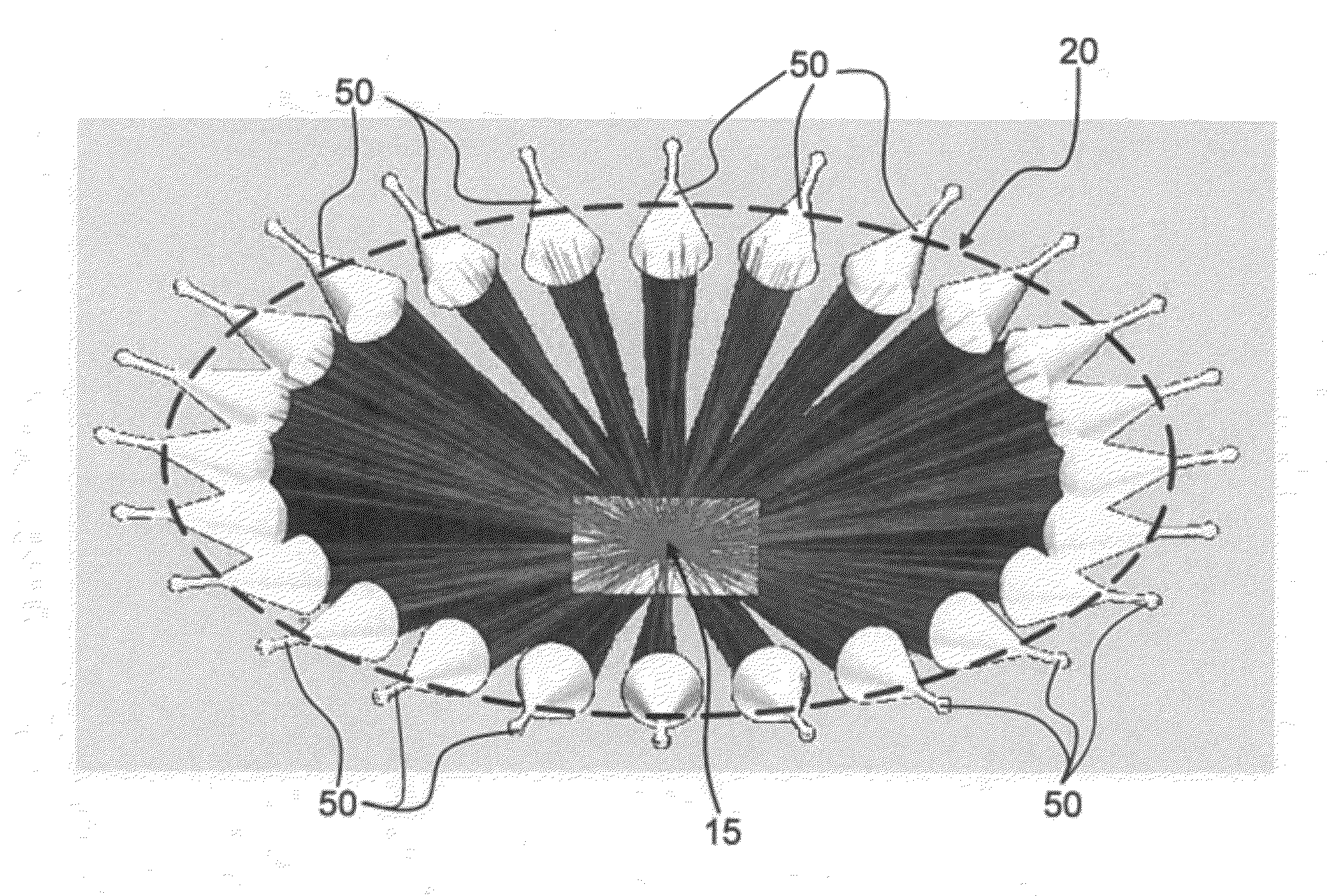
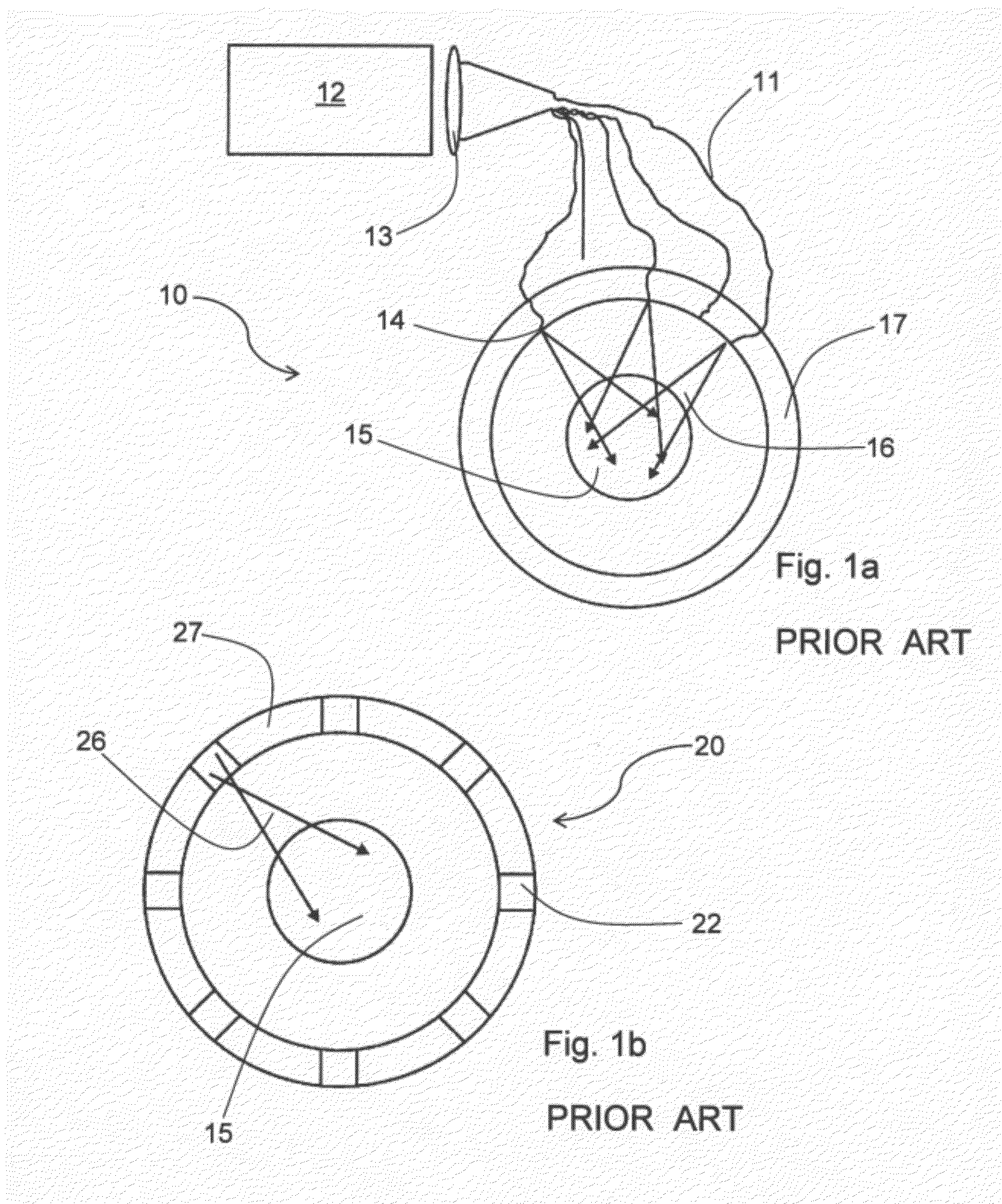
[0070]FIG. 1a shows a setup for a prior art ring light illuminator 10. An arc lamp 12 is used as a light source; light from the arc lamp 12 is coupled into plural optical fibres 11 by suitable optical elements 13 (only one such element is shown in the drawing). Ends 14 of the optical fibres 11 are arranged annularly in a ring shaped carrier 17 of the ring light illuminator 10, in such a way that they emit the light from the arc lamp 12 towards an area 15 to be illuminated circumscribed by the carrier 17. As is indicated by the cones 16, the light is emitted from the ends 14 with a considerable divergence, meaning a divergence too large for many ...


PUM


Abstract

A ring light illuminator with annularly arranged light sources is disclosed. To each light source there corresponds a light collector, a homogenizing means for light from the light source, and an anamorphic system for imaging an output of the homogenizing means into an area to be illuminated. The anamorphic system compensates deformations of a cross-sectional area of a light beam in a surface to be illuminated due to an oblique angle of incidence of the light beam onto the surface. The homogenizing means in embodiments is a rod, into which light from the light collector is directed. The end of the rod opposite the light collector is imaged by the anamorphic system into the area to be illuminated on the surface. Also disclosed is a method for illumination.

Description

CROSS REFERENCE TO RELATED APPLICATIONS[0001]This patent application claims priority of U.S. provisional patent application No. 61 / 369,632 filed Jul. 30, 2010, the application is incorporated herein by reference.FIELD OF THE INVENTION[0002]The present invention relates to a ring light illuminator.[0003]The present invention also relates to a beam shaper.[0004]The present invention also relates to a method for illumination.BACKGROUND OF THE INVENTION[0005]In many optical inspection or imaging tasks a well-defined illumination of the area to be inspected or imaged is required. For many such illumination purposes ring lights are used, for example in microscopy, where they are a common means to provide a dark field illumination. In such applications, it is desirable to restrict the area illuminated to the area of interest, and to have a homogeneous distribution of light within the area of interest. Possible light sources for example are arc lamps, LEDs (light emitting diodes), laser dio...

Claims


Application Information

Patent Timeline
Patent Type & Authority Applications(United States)
IPC IPC(8): F21V8/00F21V5/04F21V11/00F21V21/00
CPCG02B6/0008G01N21/8806G02B21/084G01N2021/8822G01N2201/0631G01N2201/0638G01N2201/062G02B27/0994G02B6/0006G02B19/0061G02B19/0028
Inventor BURGES, DACIAN
Owner KLA TENCOR TECH CORP
Why Eureka
Try Eureka