
Guide device

a technology of guide device and tip, which is applied in the field of guide device, can solve the problems of insufficient pericardium pulling to separate the pericardium from the heart, difficult to accurately determine the relative positions and difficult to accurately determine the relative position of the tip of the puncture needle and the tissu

Inactive Publication Date: 2012-07-26
OLYMPUS CORP
View PDF4 Cites 14 Cited by
  • Summary
  • Abstract
  • Description
  • Claims
  • Application Information

AI Technical Summary

Benefits of technology

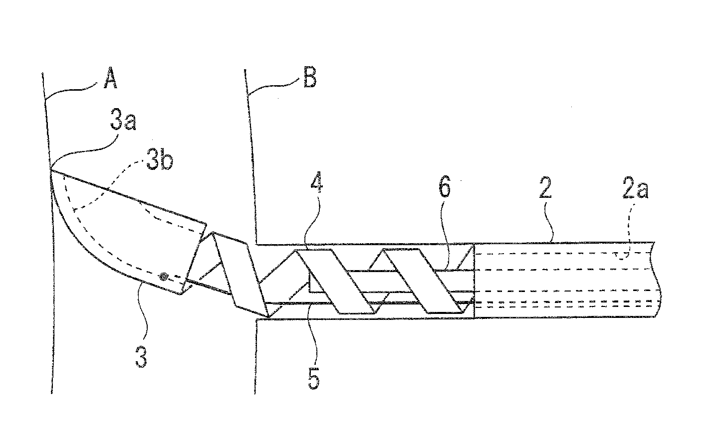
[0013]That is, it is possible to detect the displacement of the moving part with the displacement-detecting mechanism to reliably and quickly detect that the distal end of the insertion part has entered the pericardium, and it is also possible to stop further insertion of the insertion part to selectively perforate the pericardium. In addition, the insertion part can be easily advanced while cutting the body tissue with the perforating part disposed at the distal end of the insertion part, and the pericardium can be easily perforated by inserting the insertion part from the xiphoid process. In addition, the moving part displaced at the farther position is directed laterally due to the flexibility of the biasing mechanism, thereby preventing the moving part from contacting the tissue in the forward direction.
[0019]Thus, the orientation of the moving part is changed, thereby allowing the displacement thereof to be more easily detected and preventing the moving part from contacting the tissue present in the cavity in the forward direction.
[0021]Thus, the mark is moved forward relative to the insertion part as the moving part pulls the tip of the wire when the moving part is displaced from the nearby position to the farther position. This allows the movement of the moving part to be easily detected outside the patient's body.
[0023]Thus, the position and displacement of the moving part in the body can be easily visually recognized in a radioscopic image.
[0025]Thus, a radiocontrast agent is injected from the injection port into the conduit and is thereby ejected from the orifice at the distal end of the insertion part into the body. This allows the distal end of the insertion part in the body to be more reliably located.

Problems solved by technology

It is difficult, however, to accurately determine the relative positions of the tip of the puncture needle and the tissue because radioscopic images are two-dimensional.
In particular, it is extremely difficult to determine whether or not the tip of the puncture needle has reached the pericardium because the pericardium is invisible in radioscopic images.
WO 98 / 024378 are introduced from the xiphoid process into the pericardium in order to puncture the pericardium, the pericardium is combined with the inner surface of the sternum and the diaphragm near the position reached by the devices; therefore, pulling the pericardium is insufficient to separate the pericardium from the heart.
However, the devices cannot be disposed as such in the body when introduced from the xiphoid process into the pericardium.

Method used


Image

  • Guide device
  • Guide device
  • Guide device

Examples


Embodiment Construction

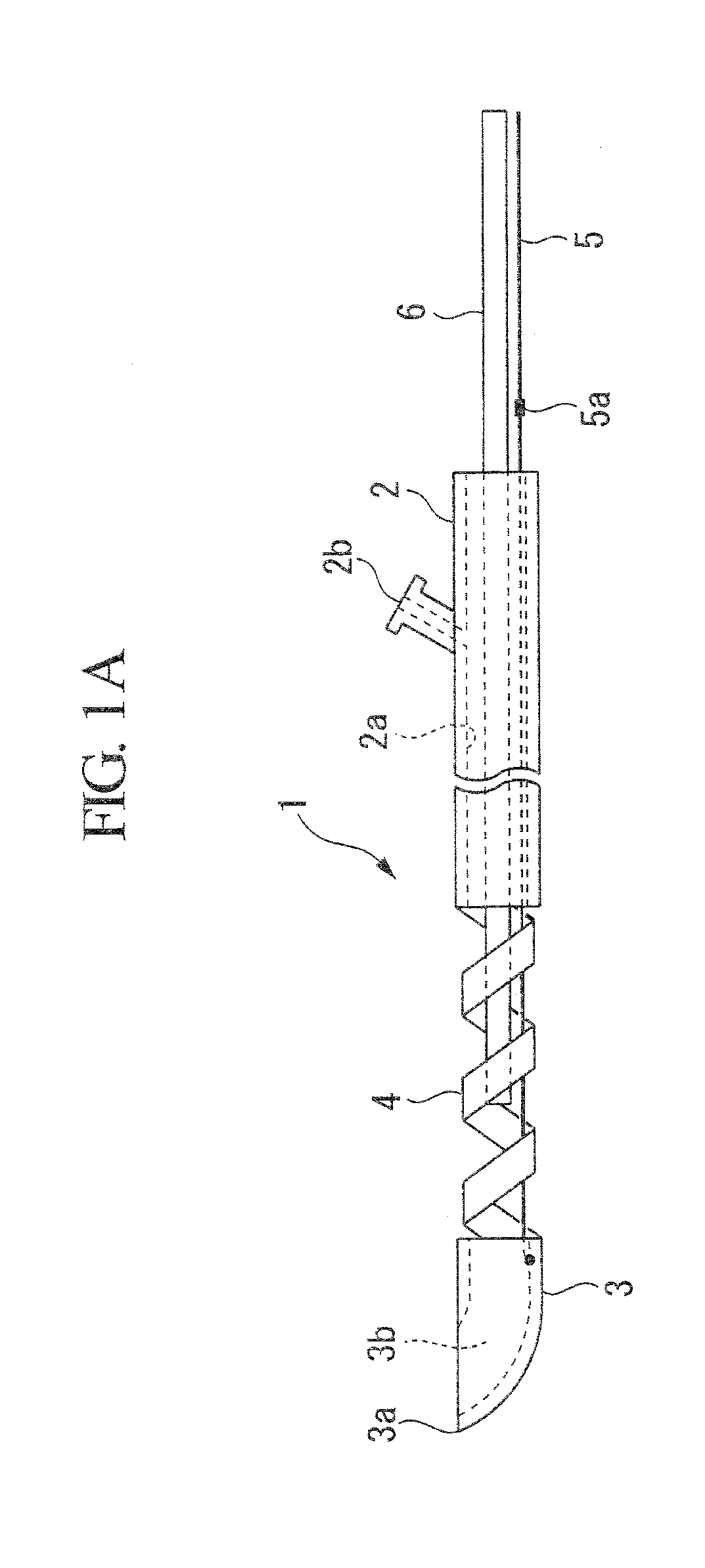
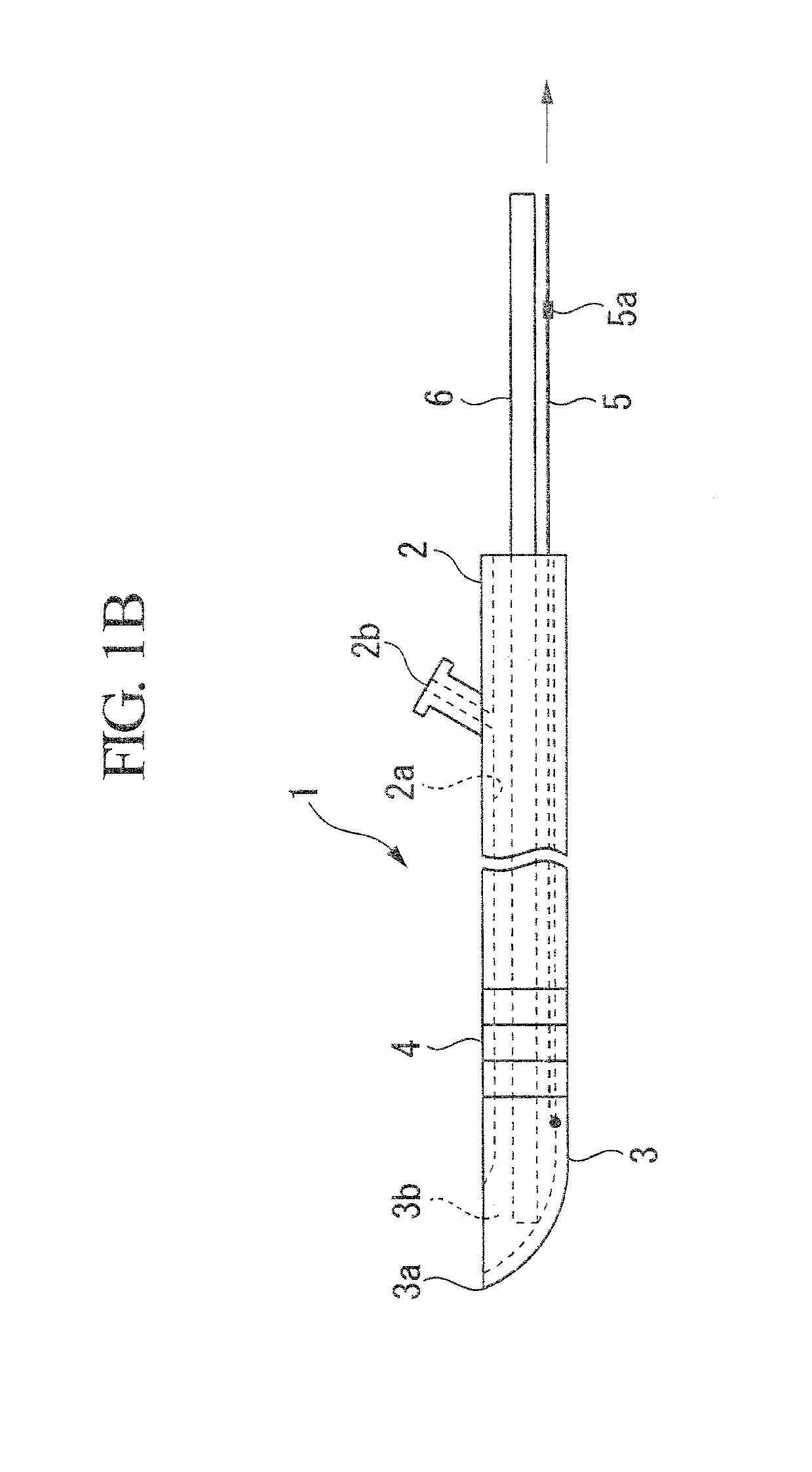
[0050]A guide device 1 according to an embodiment of the present invention will be described below with reference to the drawings.

[0051]As shown in FIGS. 1A and 1B, the guide device 1 according to this embodiment includes a cylindrical insertion part 2, a distal part (moving portion) 3 disposed on the distal side of the insertion part 2, a spring (biasing mechanism) 4 disposed between the insertion part 2 and the distal part 3, a manipulating wire (displacement-detecting mechanism, wire) 5 for moving the distal part 3 backwards and forwards, and a core bar 6 that can be inserted into and retracted from the insertion part 2.

[0052]The insertion part 2 is formed of a metal having a relatively small biological effect or a resin such as urethane, PTFE, or Duracon. The insertion part 2 has a lumen (conduit) 2a passing therethrough in the longitudinal direction. The insertion part 2 has an injection port 2b leading to the lumen 2a on the proximal side thereof. A contrast agent is injected ...


PUM


Abstract

Provided is a guide device including a cylindrical insertion part that is inserted into a body and that opens near a distal end thereof and on a proximal side thereof, a perforating part that is disposed at the distal end of the insertion part and that perforates tissue, a moving part disposed near the distal end of the insertion part so as to be displaceable between a nearby position near the insertion part and a farther position farther away from the insertion part than the nearby position, a biasing mechanism that biases the moving part in a direction away from the insertion part, and a displacement-detecting mechanism that detects displacement of the moving part in the body.

Description

CROSS-REFERENCE TO RELATED APPLICATIONS[0001]This is a continuation of International Application PCT / JP2010 / 063636, with an international filing date of Aug. 11, 2010, which is hereby incorporated by reference herein in its entirety. This application claims the benefit of Japanese Patent Application No. 2009-232468, filed Oct. 6, 2009, the content of which is incorporated herein by reference.BACKGROUND OF THE INVENTION[0002]1. Field of the Invention[0003]The present invention relates to guide devices.[0004]2. Description of Related Art[0005]In the related art, there is a known procedure for percutaneously treating the heart in heart surgery by inserting a cardiac treatment instrument that is inserted into the body into the pericardium through a hole formed in the pericardium. The insertion of the cardiac treatment instrument into the pericardium is carried out by, for example, the following steps. Initially, a puncture needle is inserted from below the xiphoid process to perforate t...

Claims


Application Information

Patent Timeline
Patent Type & Authority Applications(United States)
IPC IPC(8): A61B17/34A61B18/14A61B17/295A61B17/32
CPCA61B17/00234A61B17/3478A61B18/1445A61B19/201A61B2019/4857A61B2017/2926A61B2017/3425A61B2018/00392A61B2017/00247A61B2017/003A61B2017/00305A61M25/065A61B90/11A61B2090/032A61B2090/0811
Inventor SUGAHARA, MICHIHIROKOBAYASHI, MASAYUKIOKAZAKI, YOSHIRO
Owner OLYMPUS CORP
Learn More