Wheel bearing with sensor

a technology of sensor and wheel bearing, which is applied in the direction of instruments, force/torque/work measurement apparatus, transportation and packaging, etc., can solve the problems of sensor corrosion, output signal hysteresis, and problem of assemblability

Active Publication Date: 2012-08-02
NTN CORP
View PDF5 Cites 10 Cited by
  • Summary
  • Abstract
  • Description
  • Claims
  • Application Information

AI Technical Summary

Benefits of technology

[0041]In one embodiment of the present invention, the sensor unit may have three or more contact fixing segments and two sensors, the two sensors being fitted between the neighboring first and second contact fixing segments and between the neighboring second and third contact fixing segments, respectively, in which case the interval between the neighboring contact fixing segment or the neighboring sensors in the circumferential direction of the outer member is chosen to be (1/2+n), wherein n represents an integer, in whi

Problems solved by technology

It has, however, been found involving such a problem that since the deformation of the flange portion of the stationary ring is accompanied by a slippage in the event that a force exceeding the static frictional force between a flange surface and a knuckle, repeated application of the load may results in generation of a hysteresis in an output

Method used


Image

  • Wheel bearing with sensor
  • Wheel bearing with sensor
  • Wheel bearing with sensor

Examples


first embodiment

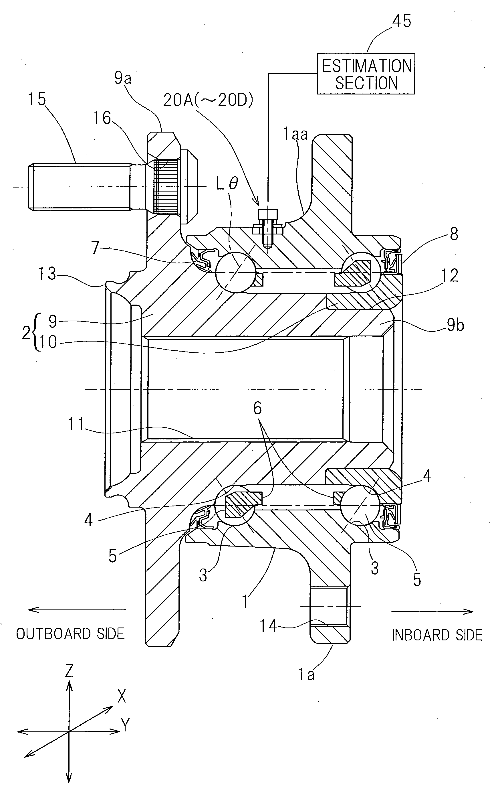
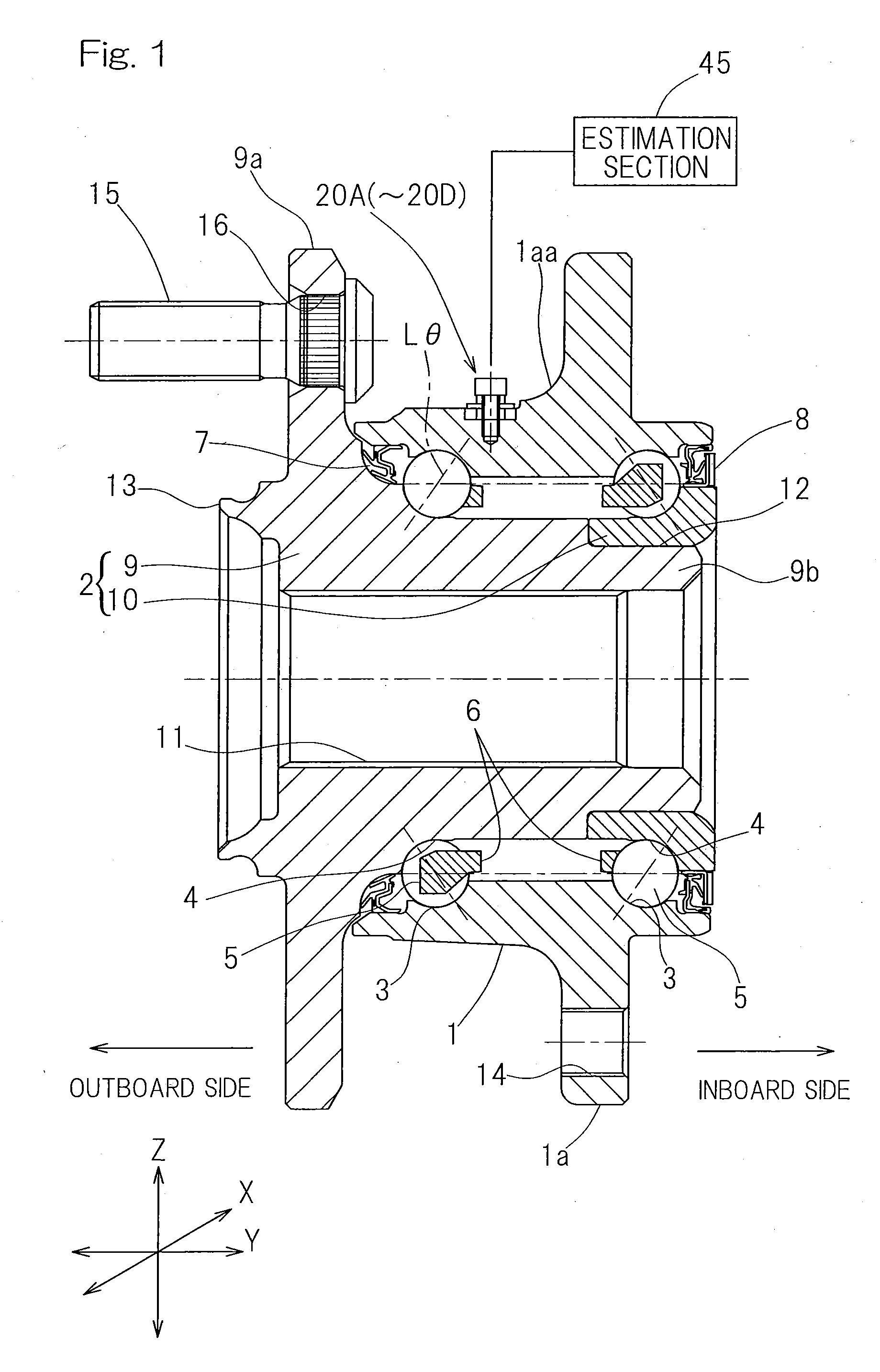
[0099]the present invention will be described in detail with particular reference to FIG. 1 to FIGS. 6A to 6C. The embodiment shown in FIG. 1 to FIGS. 6A to 6C is an inner ring rotating model of the third generation type and is applied to a wheel support bearing assembly for the support of a drive wheel. It is to be noted that in the description set forth hereinabove and hereinafter, the terms “outboard” and “inboard” are to be understood as meaning one side of the vehicle body away from the longitudinal center of the vehicle body and the other side of the vehicle body close to the longitudinal center of the vehicle body, respectively, when assembled in the vehicle body.

[0100]A bearing unit in this sensor equipped wheel support bearing assembly includes, as shown in a longitudinal sectional representation in FIG. 1, an outer ring 1 forming an outer member having an inner periphery formed with a plurality of rolling surfaces 3, an inner member 2 having an outer periphery formed with ...

second embodiment

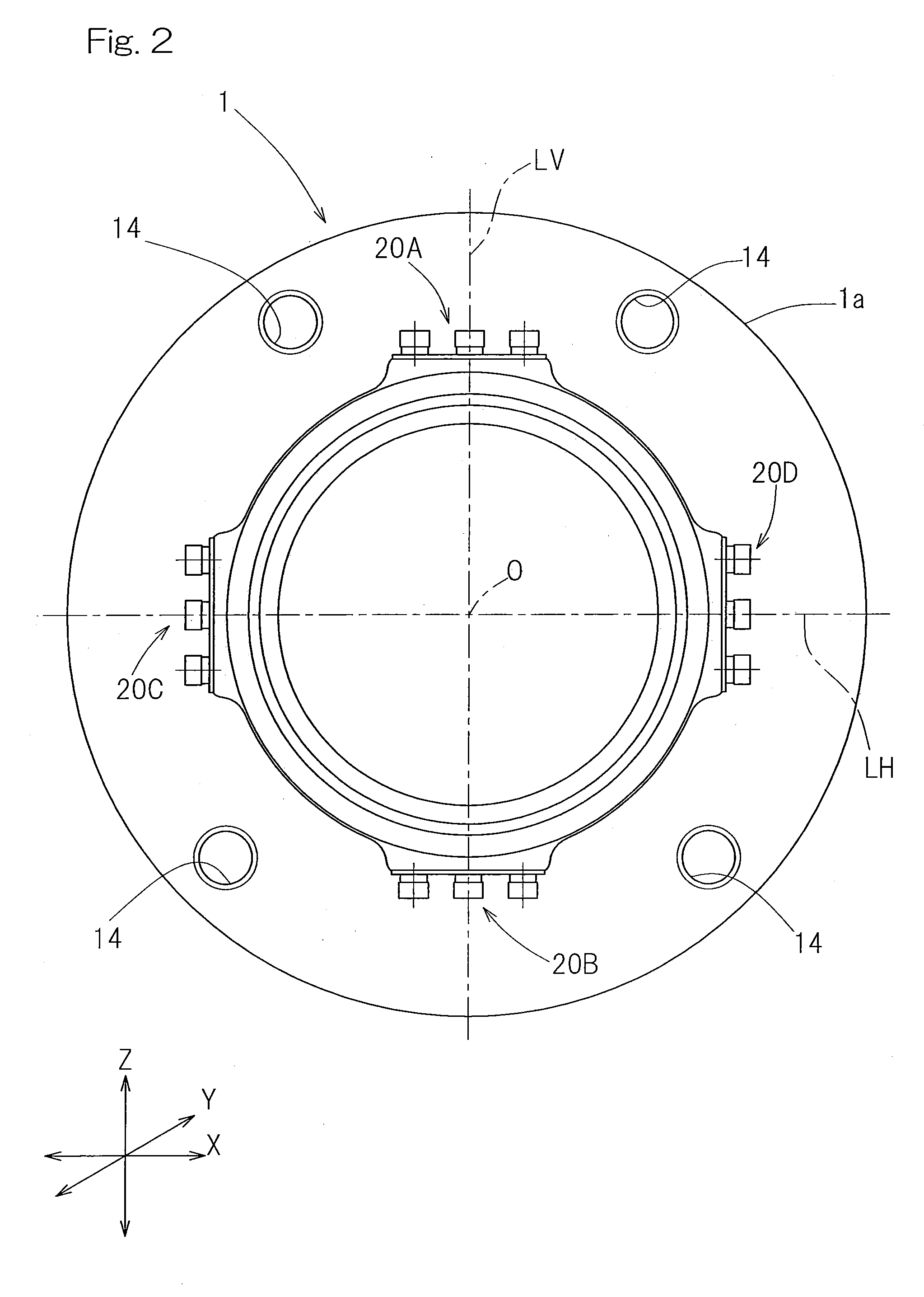
[0125]In that case, as the outer ring outer peripheral surface portion adjoining the arcuately sectioned portion 1aa on the outboard side, which area 1aa is formed in the outer periphery of the outer ring 1 so as to extend from a base end of one side of the flange 1a oriented towards the outboard side to the outer periphery of the outer ring 1, the sensor units 20A to 20D may be provided at the outer ring outer peripheral surface portion within a region axially spaced within 5 mm from a terminating end of the articulately sectioned portion 1aa such as employed in the practice of a second embodiment shown in FIG. 7. When the sites of installation of the sensor units 20A to 20D are chosen within the range spaced within 5 mm in the axial direction from the terminating end of the articulately sectioned portion 1aa in the manner described above, even when variation occurs in the temperature distribution of the outer ring 1 and the expansion • contraction amount, the influence thereof can...

fourth embodiment

[0170]FIG. 31 is a figure corresponding to FIG. 11 pertaining to the fourth embodiment and, except that it differs from FIG. 11 in respect of the position at which the sealing material 37 is applied to that portion where the signal cable drawing portion 32B is drawn, other structural features thereof are similar to those shown in FIG. 11.

[0171]In the case of this tenth embodiment, unlike the previously described fourth embodiment best shown in FIG. 10, the protective shroud 29 used to enclose the outer periphery of the outer ring 1 is so shaped as to be stepwise flared outwardly with its outer diameter increasing from the outboard side towards the inboard side. Moreover, whereas in the previously described fourth embodiment, the inboard end of the protective shroud 29 is provided with the lip member 35 made of an annular elastic element so as to extend along the open edge thereof and this lip member 35 is held in contact with the outboard oriented side face of the vehicle body fitti...


PUM


Abstract

A sensor equipped wheel support bearing assembly, in which detection error is relieved to accurately estimate load is provided. A vehicle body fitting flange of an outer member of the bearing assembly has a front elevational shape of line symmetry or of point symmetry. A sensor unit including a strain generating member having two or more contact fixing segments to be fixed to the outer member and a strain sensor is provided at an arcuately sectioned portion lying from the flange to the outer member, or an outer peripheral surface portion of the outer member adjoining to the outboard side thereof, or a position crossing a line segment passing through a center of a rolling element or a position adjoining thereto. Alternatively, a plurality of sensor units are provided on the outer periphery of the outer member in a fashion spaced circumferentially equidistantly.

Description

CROSS REFERENCE TO THE RELATED APPLICATIONS[0001]This application is a continuation application, under 35 U.S.C. §111(a), of international application No. PCT / JP2010 / 067829, filed Oct. 12, 2010, which claims priority to Japanese patent applications No. 2009-237081, filed Oct. 14, 2009, No. 2009-244303, filed Oct. 23, 2009 and No. 2009-293815, filed Dec. 25, 2009, the disclosure of which are incorporated by reference in their entirety into this application.BACKGROUND OF THE INVENTION[0002]1. Field of the Invention[0003]The present invention relates to a sensor equipped wheel support bearing assembly having a load sensor built therein for detecting a load acting on a bearing unit of a vehicle wheel.[0004]2. Description of Related Art[0005]As a technique to detect a load acting on any one of vehicle wheels of an automotive vehicle, a sensor equipped wheel support bearing assembly has been suggested in, for example, the patent document 1 listed below, in which detection is made of strai...

Claims


Application Information

Patent Timeline
IPC IPC(8): G01M15/00
CPCF16C19/186F16C19/522F16C33/586G01L5/0019F16C33/7886F16C33/805F16C2326/02F16C33/7876F16C41/00F16C2233/00
Inventor NORIMATSU, TAKAYUKIOKASAKA, MAKOTOKAWAMURA, HIROSHINISHIKAWA, KENTAROUSHIBATA, KIYOTAKE
Owner NTN CORP
Why Eureka
Try Eureka