Laser system for a microscope and method for operating a laser system for a microscope

a laser system and microscope technology, applied in the field of laser systems for microscopes, can solve the problems of high demands on the stability of light beam intensity, particularly expensive and complex laser systems, and achieve the effect of easy modulation

Inactive Publication Date: 2012-08-02
LEICA MICROSYSTEMS CMS GMBH
View PDF6 Cites 2 Cited by
  • Summary
  • Abstract
  • Description
  • Claims
  • Application Information

AI Technical Summary

Benefits of technology

[0013]The light intensity of the light source can then easily be modulated...

Problems solved by technology

Moreover, in confocal microscopy, in particular, the stability of the intensity of the light beam is subject to particularly high demands.
These requir...

Method used


Image

  • Laser system for a microscope and method for operating a laser system for a microscope
  • Laser system for a microscope and method for operating a laser system for a microscope
  • Laser system for a microscope and method for operating a laser system for a microscope

Examples


Embodiment Construction

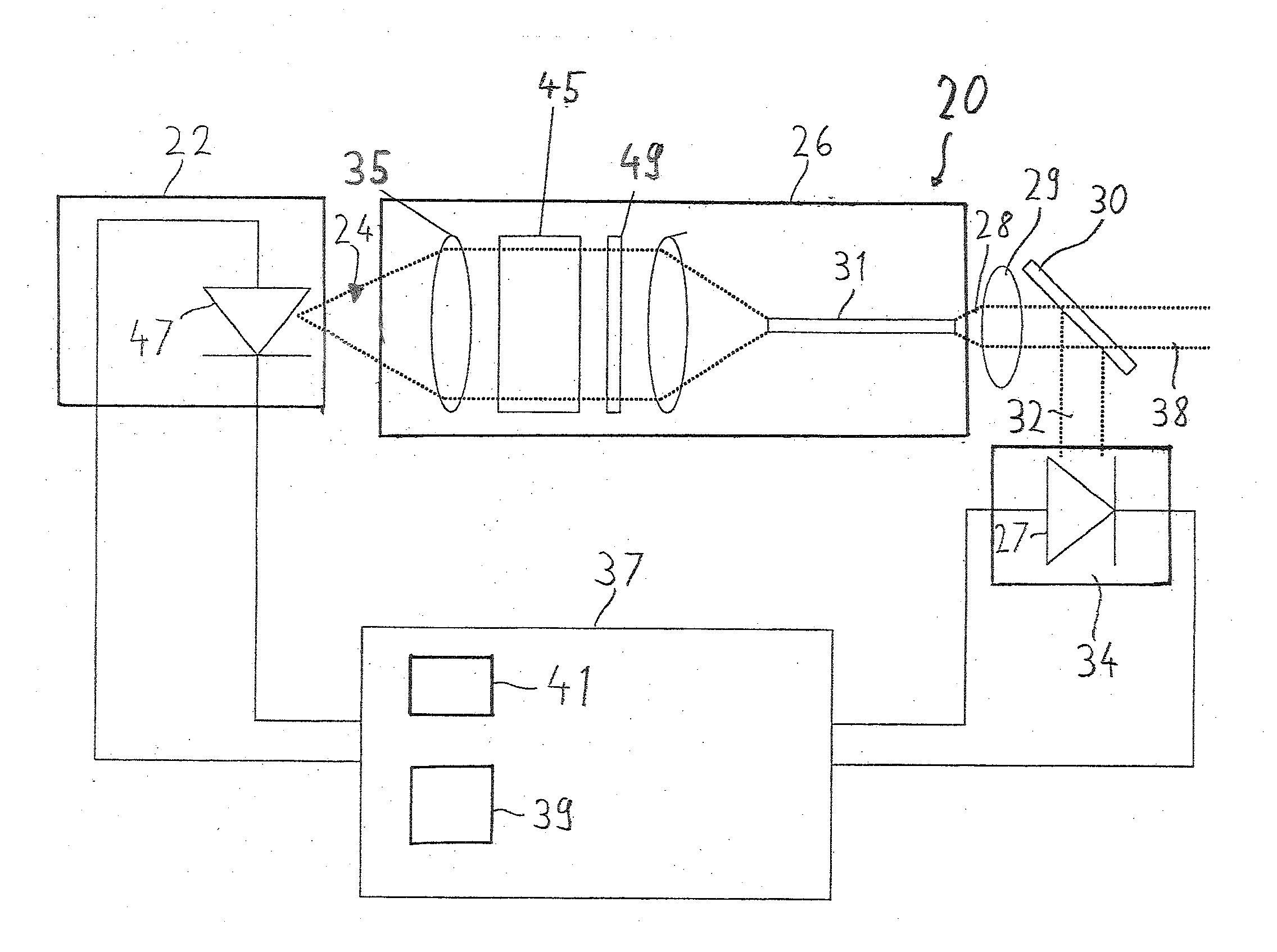
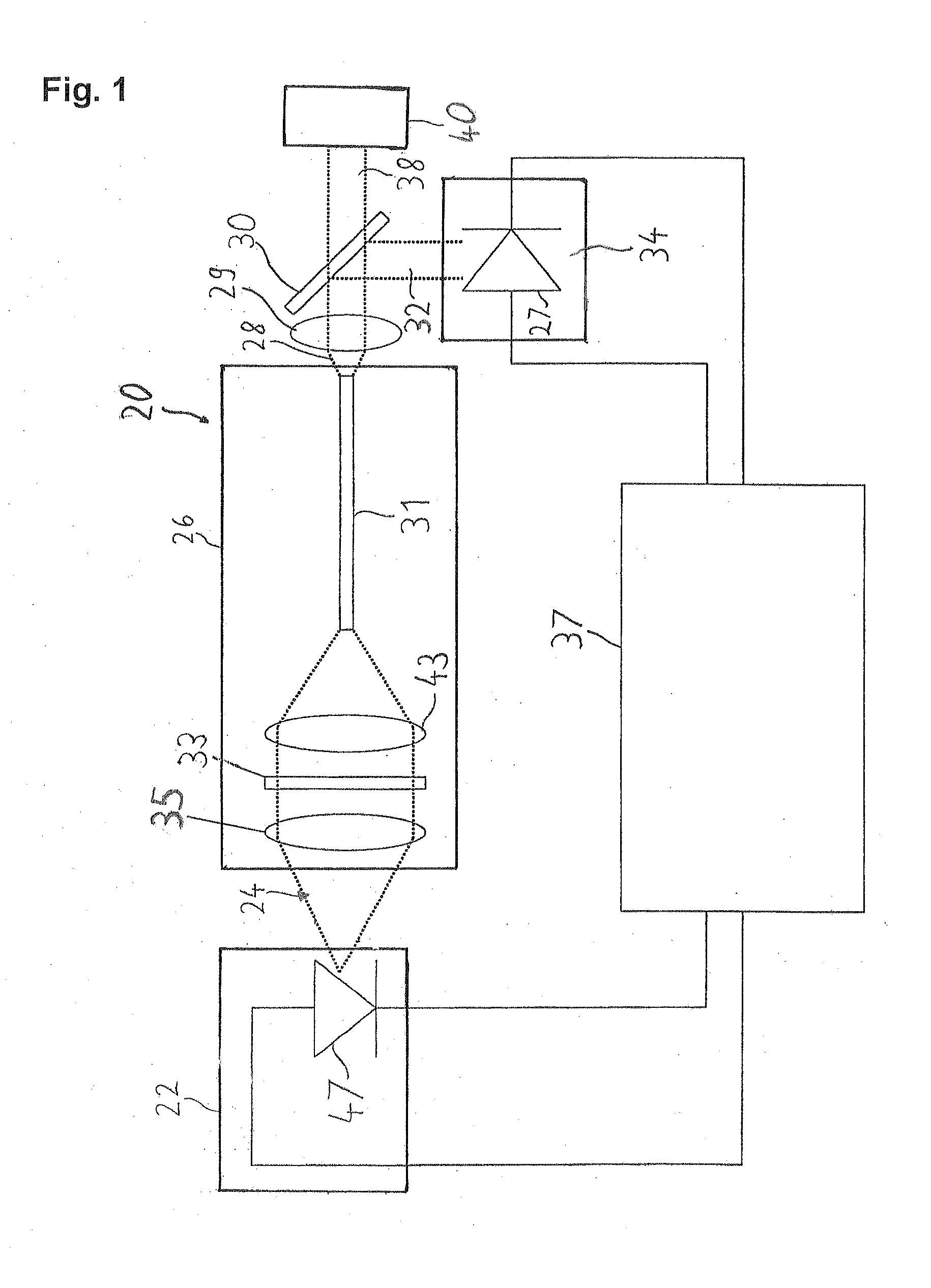
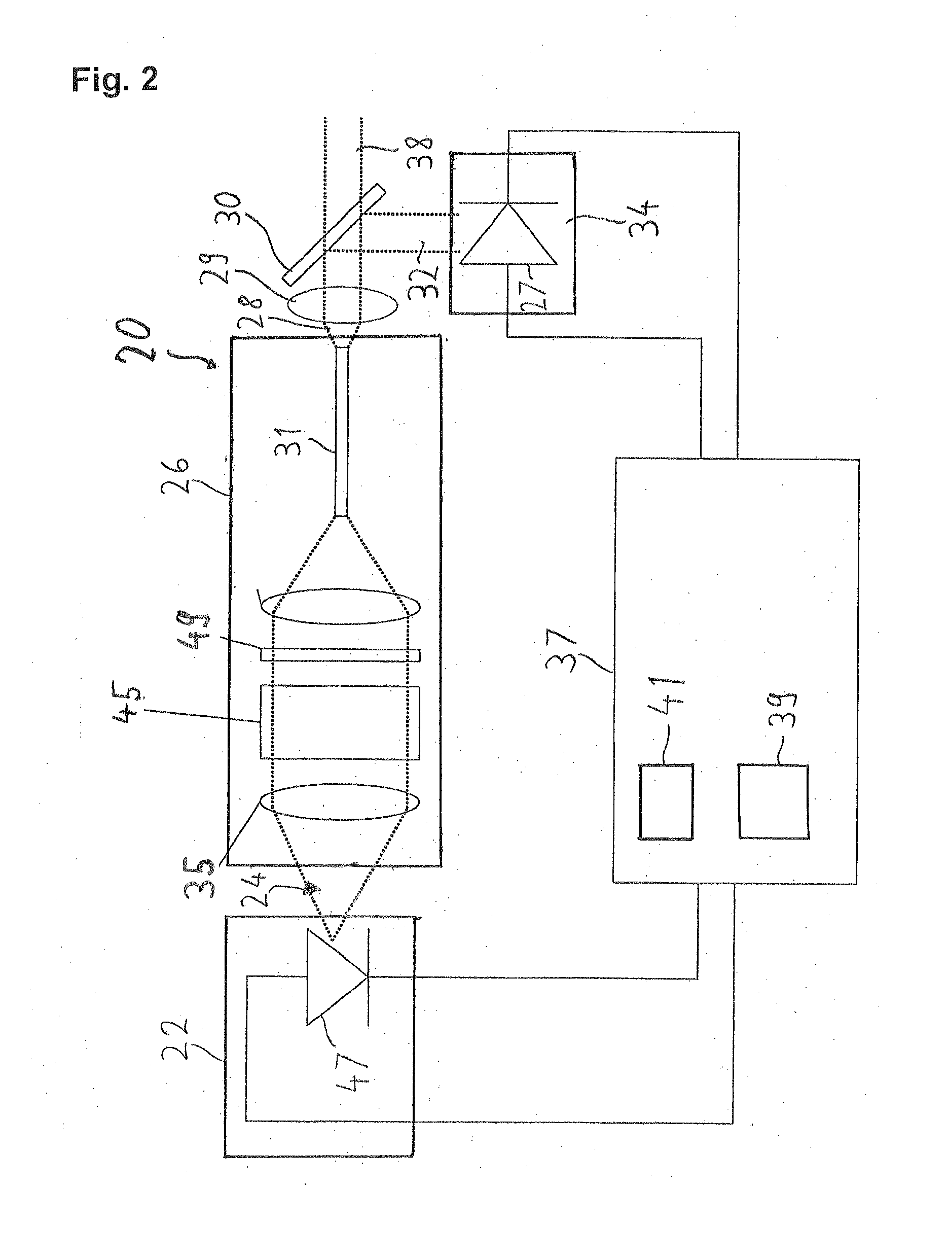
[0019]FIG. 1 shows a laser system 20 which serves particularly as a light source in a microscope, for example a confocal scanning microscope. The laser system 20 comprises a laser module 22, a beam correction device 26, a measuring element 34 and an external controller 37.

[0020]The laser module 22 produces a light beam 24. The light beam 24 passes through the beam correction device 26. The beam correction device 26 comprises two compensation elements. The compensation elements are an optical fibre 31 and a wavelength filter 33 through which the light beam 24 passes. The beam correction device 26 has an optical collimator 35. The light beam 24 is directed through the optical collimator 24 onto the wavelength filter 33. After the wavelength filter 33 the light beam 24 is directed through the optical focussing device 43 onto an axial end of the optical fibre 31 and coupled into it. A corrected light beam 28 leaves the optical fibre 31 and the beam correction device 26 at another axial ...


PUM


Abstract

The invention relates to a laser system (20) for a microscope, comprising a laser module (22), a beam correction device (26), an optical fiber (31), a measuring element (34), and an external controller (37). The laser module (22) generates a light beam (24). The light beam (24) penetrates the beam correction device (26), which corrects a deviation of an actual value of at least one parameter of the light beam (24) from a target value of the parameter. The corrected light beam (24) is coupled into the optical fiber (31). The measuring element (34) is connected downstream of the optical fiber (31) and captures an actual value (36) of the intensity of at least one partial beam (32) of the corrected light beam (24). The external controller (37), regulates the actual value (36) of the intensity to a prescribed target value for the intensity.

Description

CROSS REFERENCE TO RELATED APPLICATIONS[0001]The present application is the U.S. National Stage of International Application No. PCT / EP2010 / 065071 filed Oct. 8, 2010, which claims priority of German Application No. 10 2009 048 710.7-56 filed Oct. 8, 2009. The present application claims priority benefit of said International Application No. PCT / EP2010 / 065071 and said German Application No. 10 2009 048 710.7-56.FIELD OF THE INVENTION[0002]The invention relates to a laser system for a microscope. Moreover, the invention relates to a method for operating a laser system for a microscope.BACKGROUND OF THE INVENTION[0003]Laser systems nowadays are used in all kinds of technological fields. The lasers are regularly used for lighting purposes in which precise, high intensity light sources in point form are required. In confocal microscopy, in particular, it is important that a light beam produced by the laser system, particularly an illuminating light beam of a confocal microscope, is partic...

Claims


Application Information

Patent Timeline
IPC IPC(8): G01J1/32
CPCG02B21/06G02B21/0032
Inventor WIDZGOWSKI, BERNDSEYFRIED, VOLKERBIRK, HOLGER
Owner LEICA MICROSYSTEMS CMS GMBH
Why Eureka
Try Eureka