Network system, control apparatus and network apparatus

a control apparatus and network technology, applied in the field of network systems, can solve the problems of increasing network load, increasing network load, complication of protocols, programs, data, etc., and achieve the effect of increasing network load

Inactive Publication Date: 2012-08-02
HITACHI LTD
View PDF6 Cites 10 Cited by
  • Summary
  • Abstract
  • Description
  • Claims
  • Application Information

AI Technical Summary

Benefits of technology

[0021]It is therefore an object of this invention to lessen, in a network where a multilayer (e.g., two-layer) protocol is used and an address is specified in association with each protocol layer, overhead that is caused in the process of sharing the association relation between the addresses, in particular, a problem of increased network load due to the occurrence of broadcast and a problem of the complication and expansion of protocols, programs, data, and the like for the generation of broadcast.
[0022]In particular, an object of this invention is to eliminate the functions of generating and managing ARP messages by implementing IP over Ethernet without using an ARP message necessary to associate a MAC address and an IP address with each other. Another object of this invention is to eliminate the functions of generating and managing broadcast messages by implementing Wide Area Ethernet without using a broadcast message necessary to associate a MAC address on a VPN (upper-layer network) (upper-layer address) with the MAC address of an edge switch (a switch disposed at the entrance and a switch disposed at the exit are called edge switches) (lower-layer address).
[0024]According to an aspect of this invention, the problem of increased network load due to the occurrence of broadcast and the problem of the complication and expansion of protocols, programs, and data for the generation of broadcast are lessened.

Problems solved by technology

The first problem is an increase in network load caused by the transmission of an ARP message.
The transmission of the ARP message generates a large number of packets, thereby creating the problem of increased network load.
The second problem is the complication of protocols, programs, data, and the like.
This causes the problem of complicating protocols, programs, data, and the like for transmitting / receiving packets.

Method used


Image

  • Network system, control apparatus and network apparatus
  • Network system, control apparatus and network apparatus
  • Network system, control apparatus and network apparatus

Examples


first embodiment

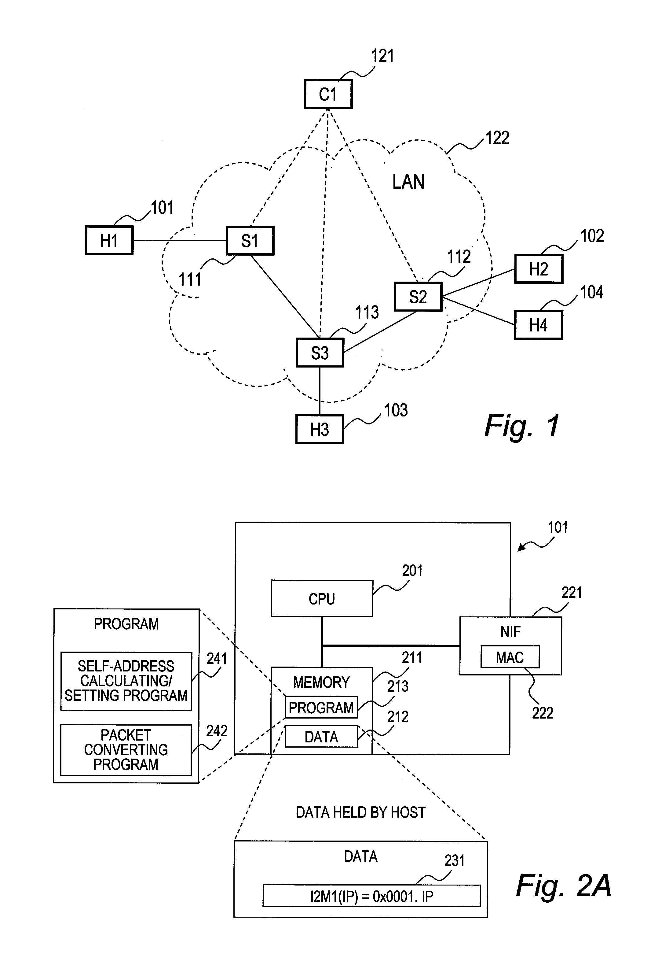
[0047]FIG. 1 is a block diagram illustrating the configuration of a network according to the first embodiment of this invention.

[0048]The network of the first embodiment includes host computers H1 (101), H2 (102), H3 (103), and H4 (104), switches S1 (111), S2 (112), and S3 (113), an address distributing server C1 (121), and a LAN 122. The LAN 122 is Ethernet implemented by the switches S1 (111), S2 (112), and S3 (113). The switches S1 (111), S2 (112), and S3 (113) have a function of a LAN switch in Ethernet.

[0049]The host computer H1 (101) is connected to the switch S1 (111). The host computers H2 (102) and H4 (104) are connected to the switch S2 (112). The host computer H3 (103) is connected to the switch S3 (113).

[0050]The address distributing server C1 (121) is connected to one of the switches S described above. This enables the address distributing server C1 (121) to communicate to / from any of the host computers H1 (101), H2 (102), H3 (103) and H4 (104).

[0051]In the first embodi...

second embodiment

[0145]A second embodiment of this invention is described below.

[0146]FIG. 7 is a block diagram illustrating the configuration of a network according to the second embodiment of this invention.

[0147]The network of the second embodiment includes a wide area network (WAN) 720, WAN switches S21 (711), S22 (712), and S23 (713), an address distributing server C11 (721), LAN switches G11 (724), G12 (751), G13 (731), G14 (741), and G15 (761), host computers H11 (722), H12 (752), H13 (732), H15 (742), H16 (743), and H17 (762), and virtual network sites 1-1 (701), 1-2 (702), 1-3(703), 2-1 (704), and 2-2 (705).

[0148]The WAN 720 is implemented by WAN switches S21 (711), S22 (712), and S23 (713). The WAN switches S21 (711), S22 (712), and S23 (713) have the function of a normal Ethernet LAN switch and also have the function of a gateway between a LAN and a WAN. This gateway function is described later with reference to FIG. 13.

[0149]The WAN switch S21 (711) is connected to the virtual network si...


PUM


Abstract

It is provided a network system comprising a plurality of computers and a control apparatus coupled to the plurality of computers via a plurality of network apparatuses. The control apparatus holds a plurality of first addresses and conversion rules for converting each of the plurality of first addresses into a second address, extracts one of the plurality of first addresses and one of the conversion rules when requested by one of the plurality of computers, and transmits the extracted one of the plurality of first addresses and the extracted one of the conversion rules to the one of the plurality of computers that has issued the request. The one of the plurality of computers that has issued the request converts the one of the plurality of first addresses into the second address by using received conversion rule, and holds the converted second address.

Description

CLAIM OF PRIORITY[0001]The present application claims priority from Japanese patent application JP 2011-016728 filed on Jan. 28, 2011, the content of which is hereby incorporated by reference into this application.BACKGROUND OF THE INVENTION[0002]This invention relates to a network system, and more particularly, to a network system that transmits / receives a packet containing a destination address and a source address.[0003]In packet communication, packets can be communicated without following a physical network protocol by using a logical network protocol separate from the physical network protocol.[0004]In order to communicate packets in a system that uses such a two-layer protocol (i.e., a physical protocol and a logical protocol), a sender address and a receiver address need to be specified for each of the two protocol layers, and the specified addresses further need to be associated between the two protocol layers. Specifically, a sender address specified for one protocol layer ...

Claims


Application Information

Patent Timeline
Patent Type & Authority Applications(United States)
IPC IPC(8): G06F15/173H04L12/70
CPCH04L12/4641
Inventor KANADA, YASUSHIKASUGAI, YASUSHI
Owner HITACHI LTD
Why Eureka
Try Eureka