Brake control device

a technology of brake control and control device, which is applied in the direction of brake control system, brake components, braking system, etc., can solve the problems of increasing the frequency the inability of electricly operated pumps to operate at low voltage, and the inability to stop the operation of anti-lock brake control

Active Publication Date: 2012-08-09
BOSCH CORP +1
View PDF8 Cites 26 Cited by
  • Summary
  • Abstract
  • Description
  • Claims
  • Application Information

AI Technical Summary

Benefits of technology

[0009]Further, the front and rear wheel interlocking brake system shares the hydraulic circuit and the electrically-operated pump with the anti-lock brake system so that a load applied to the electrically-operated pump is further increased. This creates a situation where it is inevitably necessary to stop anti-lock brake control is steadily increasing frequency.
[0010]It is an object of the present invention to provide a brake control device which can overcome the drawbacks of the above-mentioned prior art, and can perform both an interlocking brake control and an antilock brake control, and can perform the anti-lock brake control even when a voltage of electric power supplied to an electrically-operated pump is lowered.

Problems solved by technology

However, in the brake control device of the above-mentioned prior art where an anti-lock brake control is stopped when a voltage is lowered, an electrically-operated pump cannot be operated at a low voltage.
This creates a situation where it is inevitably necessary to stop anti-lock brake control is steadily increasing frequency.

Method used


Image

  • Brake control device
  • Brake control device
  • Brake control device

Examples


Embodiment Construction

[0021]Hereinafter, a preferred embodiment of the invention is explained in conjunction with drawings.

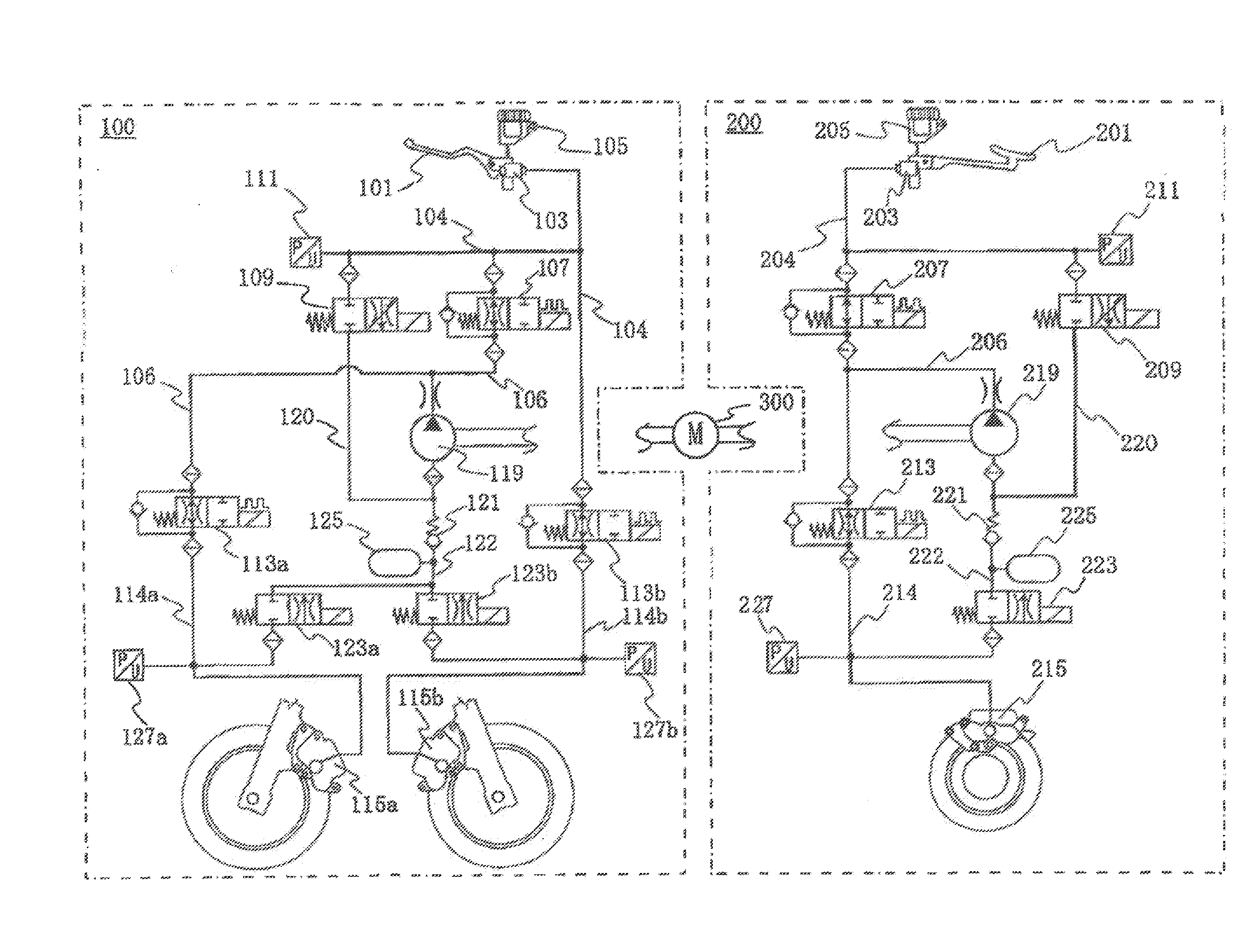
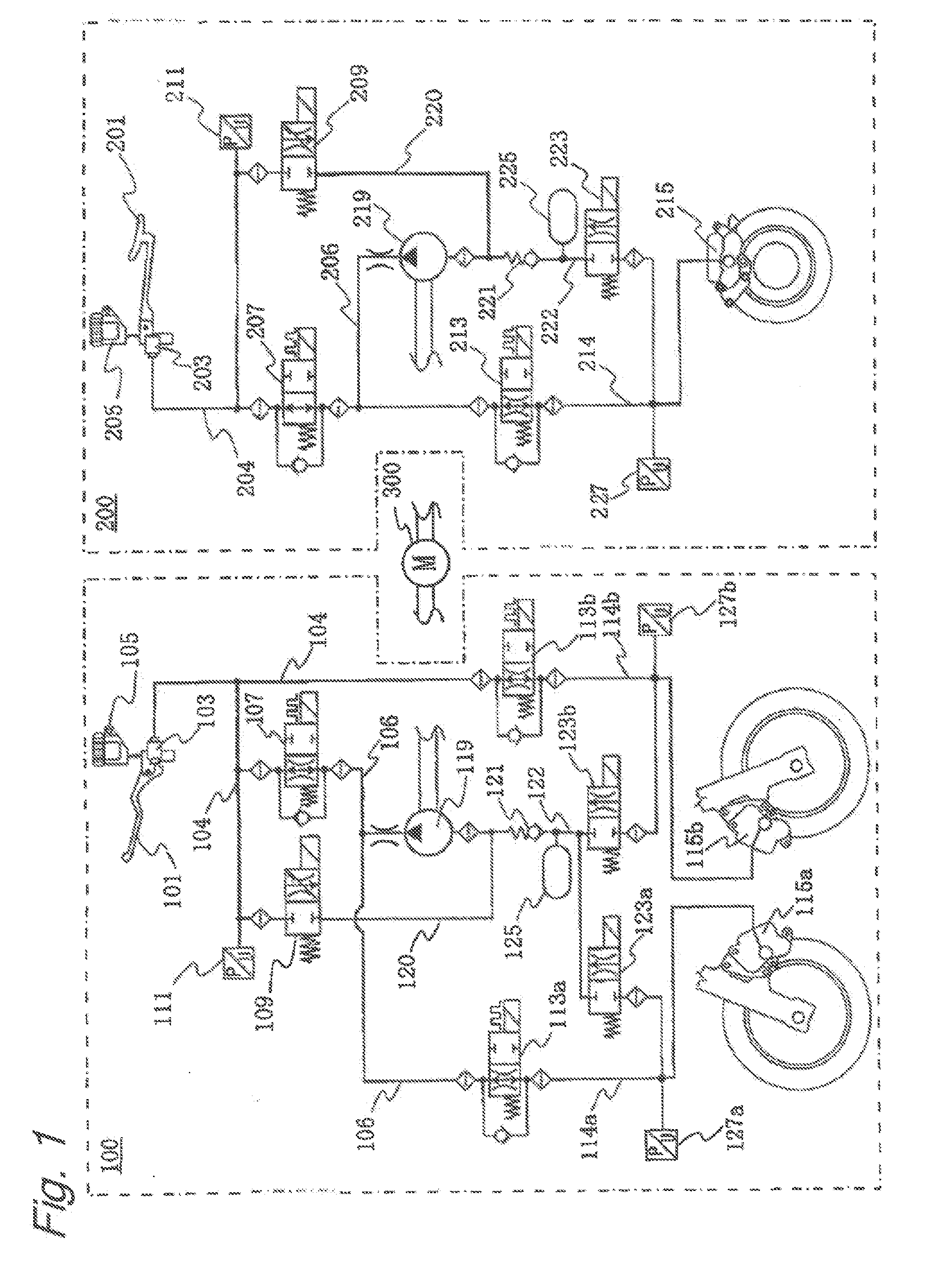
[0022]FIG. 1 shows a hydraulic circuit of a brake system of this embodiment. This brake system is constituted of a front wheel hydraulic circuit 100, a rear wheel hydraulic circuit 200, and a DC motor 300 which drives hydraulic pumps of the front wheel hydraulic circuit 100 and the rear wheel hydraulic circuit 200 respectively. The hydraulic circuit is filled with a brake fluid. In this embodiment, the electrically-operated pump is constituted of a front-wheel-side hydraulic pump 119, a rear-wheel-side hydraulic pump 219 and the DC motor 300.

[0023]Firstly, the architecture of the front wheel hydraulic circuit 100 is explained. The front wheel hydraulic circuit 100 includes a brake lever 101 which a rider manipulates with his right hand, a front-wheel-side master cylinder 103 which is pressurized when the brake lever 101 is manipulated, a reservoir 105 for the front-wheel-side master ...


PUM


Abstract

A brake control device for a brake system. The control device can perform both an interlocking brake control and an antilock brake control. The brake system includes a front-wheel hydraulic circuit, a front-wheel-side braking part; a rear-wheel hydraulic circuit, a rear-wheel-side braking part; and an electrically-operated pump which pressurizes the brake fluid. The brake control device includes a usual voltage mode where the interlocking brake control or the anti-lock brake control is performed when the supply voltage is a first voltage or more, and a low voltage mode where at least one of the interlocking brake control and the anti-lock brake control is performed in a limited manner when the supplied voltage is a second, lower voltage. An operation mode is changed from the usual voltage mode to the low voltage mode when it is determined that the supply voltage becomes lower than the first voltage.

Description

BACKGROUND OF THE INVENTION[0001]The present invention relates to a brake control device of a brake system which performs an interlocking brake control of a front-wheel-side brake and a rear-wheel-side brake, and an anti-lock brake control.[0002]Conventionally, there has been known a brake control device of a brake system which performs an anti-lock brake control using an anti-lock brake system (ABS) by controlling a fluid pressure of a brake fluid supplied to a braking part by a hydraulic circuit. In this type of brake control device, a pressure of a brake fluid in the hydraulic circuit is increased by driving an electrically-operated pump provided to the hydraulic circuit. Usually, when a supply voltage supplied to the electrically-operated pump is lowered, discharge capacity of the electrically-operated pump is lowered. When a discharge amount of brake fluid from the electrically-operated pump cannot be maintained at an amount sufficient for performing an anti-lock brake control ...

Claims


Application Information

Patent Timeline
Patent Type & Authority Applications(United States)
IPC IPC(8): B60T8/176
CPCB60T8/3225B60T8/4036B60T8/404B60T8/4072B60T8/885B60T17/02B60T13/741B60T2270/414B60T8/261B60T13/14B60T13/146B60T13/662B60T13/686B60T17/221
Inventor WAIDA, KAZUMAJINO, KENICHIKOKAWA, MANABUIWATSUKI, JUNYAONO, SHUNSAKU
Owner BOSCH CORP
Why Eureka
Try Eureka