Wireless power transmission system

a transmission system and wireless technology, applied in the direction of charging stations, electric devices, transportation and packaging, etc., can solve the problems of small electric power, and achieve the effect of improving the convenience of everyday li

Inactive Publication Date: 2012-08-09
TDK CORPARATION
View PDF5 Cites 12 Cited by
  • Summary
  • Abstract
  • Description
  • Claims
  • Application Information

AI Technical Summary

Benefits of technology

[0019]The transparency of the light control glass is controlled by wireless power feeding, so that it is easy to simplify the wiring structure. Further, in the case of a magnetic resonance type, the feeding coil and receiving coil need not face each other with a small distance, the installation position of the light control glass is less restrained by the position of the feeding coil.
[0021]The receiving coil and loading coil may be installed so as to surround the light control glass. The larger the coil area, the easier the receiving coil or loading coil can receive AC power. By installing these coils so as to surround the light control glass, a sufficient coil area can be ensured. Further, by integrating the receiving coil or loading coil with the glass frame (the frame part of the glass area) of the light control glass, it is possible to prevent the visual appearance from being impaired.
[0030]According to the present invention, the advantages of wireless power feeding of a magnetic resonance type can be made to lead to improvement of convenience of everyday life.

Problems solved by technology

The type (B) utilizing radio wave is available in a long range; however, it has small electric power.

Method used


Image

  • Wireless power transmission system
  • Wireless power transmission system
  • Wireless power transmission system

Examples


first embodiment

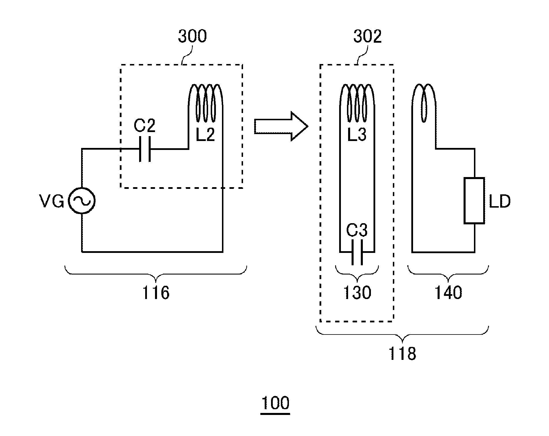
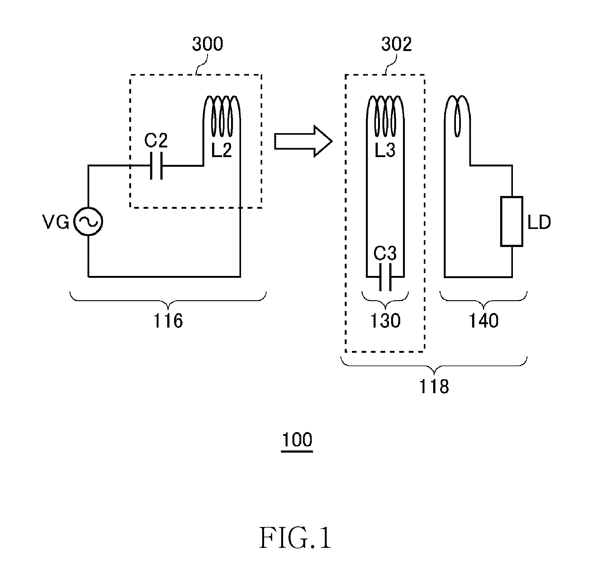
[0050]FIG. 1 is a view illustrating operation principle of a wireless power transmission system 100 according to the first embodiment. The wireless power transmission system 100 in the first embodiment includes a wireless power feeder 116 and a wireless power receiver 118. The wireless power feeder 116 includes a power feeding LC resonance circuit 300. The wireless power receiver 118 includes a receiving coil circuit 130 and a loading circuit 140. A power receiving LC resonance circuit 302 is formed by the receiving coil circuit 130.

[0051]The power feeding LC resonance circuit 300 includes a capacitor C2 and a feeding coil L2. The power receiving LC resonance circuit 302 includes a capacitor C3 and a receiving coil L3. The values of the capacitor C2, feeding coil L2, capacitor C3, and receiving coil L3 are set such that the resonance frequencies of the feeding LC resonance circuit 300 and receiving LC resonance circuit 302 coincide with each other in a state where the feeding coil L...

second embodiment

[0091]FIG. 16 is a view illustrating operation principle of the wireless power transmission system 100 according to a second embodiment. As in the case of the first embodiment, the wireless power transmission system 100 according to the second embodiment includes the wireless power feeder 116 and wireless power receiver 118. However, although the wireless power receiver 118 includes the power receiving LC resonance circuit 302, the wireless power feeder 116 does not include the power feeding LC resonance circuit 300. That is, the feeding coil L2 does not constitute a part of the LC resonance circuit. More specifically, the feeding coil L2 does not form any resonance circuit with other circuit elements included in the wireless power feeder 116. No capacitor is connected in series or in parallel to the feeding coil L2. Thus, the feeding coil L2 does not resonate in a frequency at which power transmission is performed.

[0092]The power feeding source VG supplies AC current of the resonan...


PUM

PropertyMeasurementUnit
drive frequencyaaaaaaaaaa
resonance frequency fr1aaaaaaaaaa

Abstract

A wireless power transmission system aims to feed power by wireless from a feeding coil to a receiving coil using a magnetic field resonance phenomenon between the feeding coil and receiving coil. The wireless power transmission system includes the feeding coil, receiving coil, a loading coil, and a power transmission control circuit. The power transmission control circuit supplies AC power to the feeding coil so as to make the feeding coil feed the AC power to the receiving coil. The loading coil is magnetically coupled to the receiving coil to receive the AC power from the receiving coil. A light control glass receives the AC power from the loading coil. The transparency of the light control glass is changed by the AC power received by the loading coil.

Description

BACKGROUND OF THE INVENTION[0001]1. Field of the Invention[0002]The present invention relates to wireless power feeding and, more particularly, to its application to living space.[0003]2. Description of Related Art[0004]A wireless power feeding technique of feeding power without a power cord is now attracting attention. The current wireless power feeding technique is roughly divided into three: (A) type utilizing electromagnetic induction (for short range); (B) type utilizing radio wave (for long range); and (C) type utilizing resonance phenomenon of magnetic field (for intermediate range).[0005]The type (A) utilizing electromagnetic induction has generally been employed in familiar home appliances such as an electric shaver; however, it can be effective only in a short range. The type (B) utilizing radio wave is available in a long range; however, it has small electric power. The type (C) utilizing resonance phenomenon is a comparatively new technique and is of particular interest ...

Claims


Application Information

Patent Timeline
Patent Type & Authority Applications(United States)
IPC IPC(8): B60L1/00H01F38/14
CPCB60L11/182B60L11/1831B60L11/1833B60L2210/30B60L2210/40H01F38/14Y02T90/121Y02T10/7241Y02T90/125Y02T90/12Y02T90/14Y02T90/127Y02T90/122Y02T10/7005Y02T10/7072B60L53/39B60L53/36B60L53/126Y02T10/72Y02T10/70
Inventor URANO, TAKASHI
Owner TDK CORPARATION
Why Eureka
Try Eureka