
Self-powered light bar

a self-powered, light-bar technology, applied in the direction of electric devices, lighting and heating apparatuses, instruments, etc., can solve the problems of affecting the operation of the light-bar, the inability to operate continuously, and the inability to produce energy by the alternator, etc., to achieve high data rates

Active Publication Date: 2012-08-09
FEDERAL SIGNAL CORPORATION
View PDF17 Cites 41 Cited by
  • Summary
  • Abstract
  • Description
  • Claims
  • Application Information

AI Technical Summary

Benefits of technology

[0015]In another embodiment, the supplement power source is both an alternative power source and also a source of energy for charging the battery associated with the solar cells. In this embodiment, the battery of the vehicle's power train trickle charges the battery of the emergency warning device. In the course of a vehicle's normal operation, the emergency warning device is typically off for a large portion of the time the vehicle is in use. During that time, the excess energy generated by the power train of the vehicle charges the battery of the device. The alternator of the vehicle, which is the source of power for all of the electrical devices of the vehicle, usually generates more energy than required to power the electrical devices of the vehicle. The excess energy first goes to recharge the battery of the vehicle's power train. Once the battery is fully charged, however, the potential production of energy by the alternator is largely wasted. By using the otherwise wasted potential extra energy to trickle charge the battery associated with the emergency warning device during normal operation of the vehicle, the device can approach a state in which it can operate indefinitely without requiring it be taken out of operation in order to recharge the battery. In one implementation of this embodiment, the supplemental power is aimed at only trickle charging the battery and, therefore, the connection to the warning device can be constructed to handle relatively low power levels, making the connection relatively small and easy to install.
[0018]For control signals, in order to avoid fishing wiring from a control head mounted in the interior of the vehicle to the equipment in the light bar, the connection between the control head and the light bar is preferably a wireless connection. All wiring is avoided if the emergency warning device either relies exclusively on the solar cells and the associated battery or provides a wireless energy coupling.
[0020]In one embodiment of the invention, the light bar houses at least one transceiver for communicating information gathered from sensors (preferably also in the light bar) over a wireless network. In order to enable real time communication of information demanding high data rates, the transceiver is a broadband device such as a Wi-Fi transceiver. Broadband transceivers allow for real time transmission and reception of information such as video feeds and detailed maps of buildings.

Problems solved by technology

Once the battery is fully charged, however, the potential production of energy by the alternator is largely wasted.
Obviously, these devices demand more energy than if the emergency warning device supported only lights.
But these device also are unlikely to be operated continuously and, therefore, their inclusion into the emergency warning device may not prevent the device from operating without the need to be periodically taken out of service to charge the battery.

Method used


Image

  • Self-powered light bar
  • Self-powered light bar
  • Self-powered light bar

Examples


Embodiment Construction

[0050]The following description is intended to convey the operation of exemplary embodiments of the invention to those skilled in the art. It will be appreciated that this description is intended to aid the reader, not to limit the invention. As such, references to a feature or aspect of the invention are intended to describe a feature or aspect of an embodiment of the invention, not to imply that every embodiment of the invention must have the described characteristic.

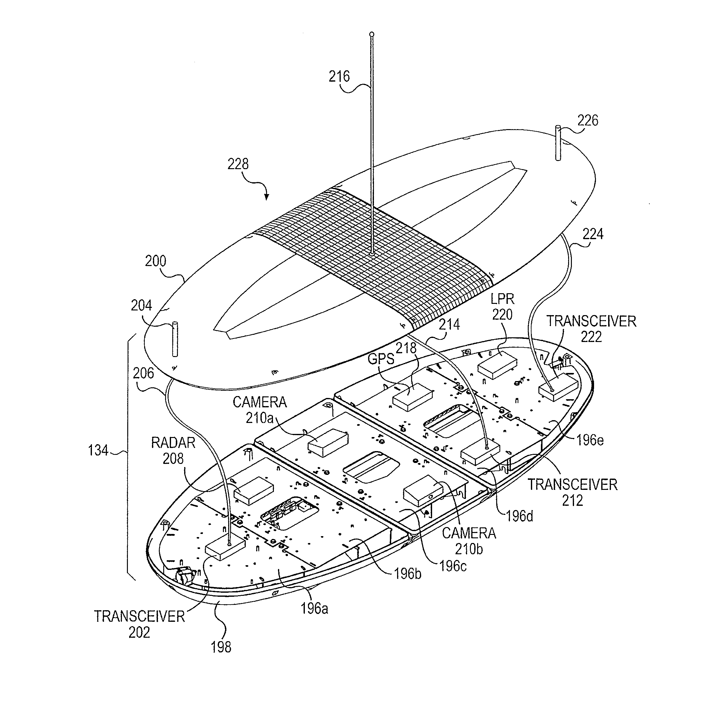
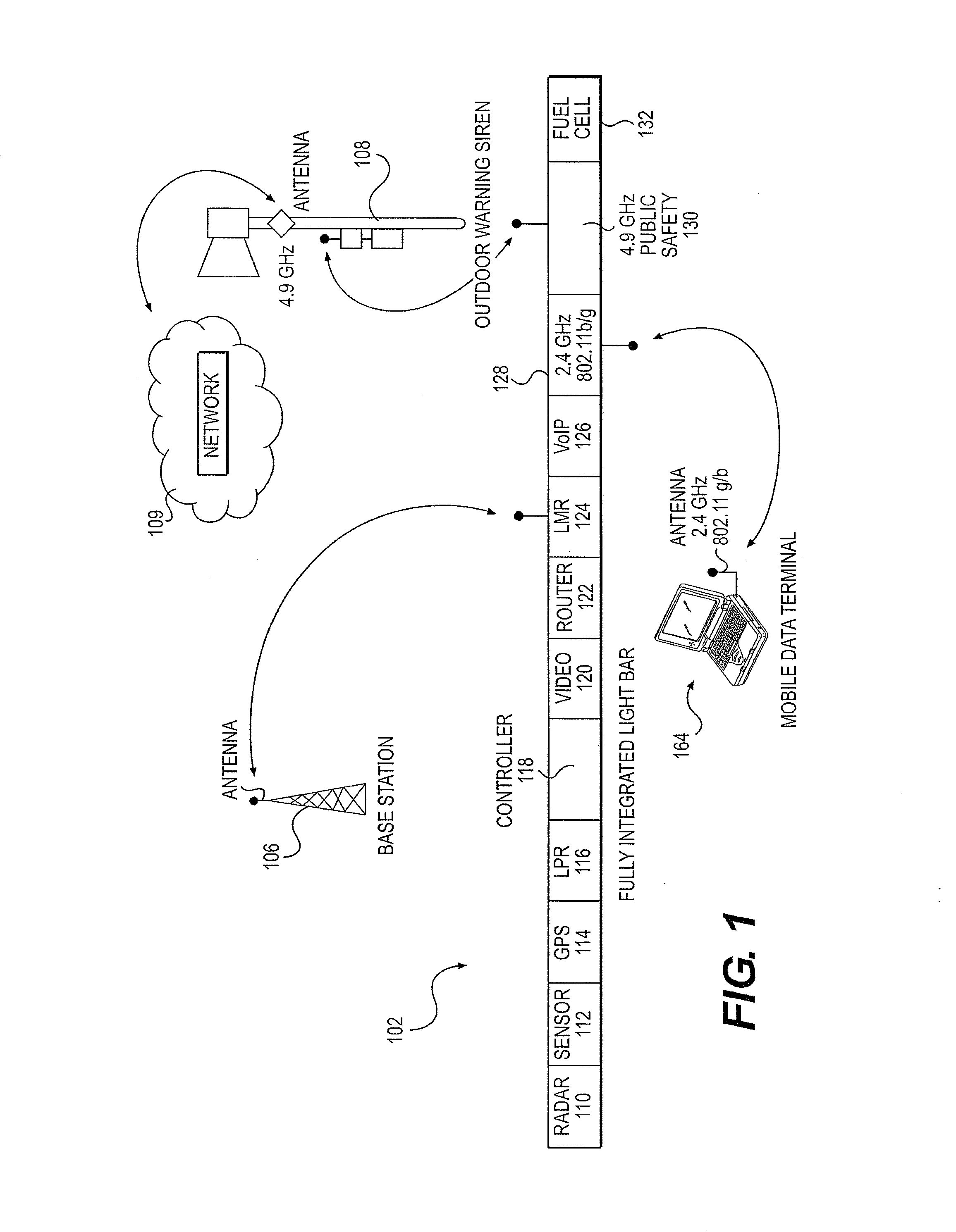
[0051]Turning to the drawings and referring first to FIG. 1, an emergency device 102 is in wireless communication with a mobile data terminal 164, a base station 106 and an outdoor warning siren 108. The emergency device 102 contains a number of monitoring, warning and response systems as needed based on its deployment. For example, in one embodiment of the invention, the emergency device 102 is attached to a police vehicle. When it is attached to a police vehicle, the emergency device 102 likely includes modules othe...


PUM


Abstract

An emergency system for a vehicle integrates many disparate equipment into single housing, including the power supply for the equipment. In one embodiment of the invention, the emergency system is a light bar. The light bar houses a power source comprising solar cell panels, a Lithium-Ion battery pack and a connection to an external supply such as the vehicle's electrical power. Energy for operating the light bar is provided by one or more of the power sources, depending on operating conditions of the light bar and each of the power sources.

Description

CROSS-REFERENCE TO RELATED APPLICATIONS[0001]This application claims the benefit of U.S. Provisional Patent Application No. 61 / 225,479, filed on Jul. 14, 2009, which is hereby incorporated by reference in its entirety.[0002]This application is a continuation-in-part of co-pending U.S. patent application Ser. Nos. 11 / 548,209 entitled “Fully Integrated Light Bar,” filed Oct. 10, 2006, and 12 / 350,506 entitled “Light Bar And Method For Making,” filed Jan. 8, 2009, which is in turn a continuation of U.S. patent application Ser. No. 11 / 394,752, having the same title and filed on Mar. 31, 2006 (now U.S. Pat. No. 7,476,013). Both applications and the issued patent are hereby incorporated by reference in their entireties and for everything they describe.BACKGROUND OF THE INVENTION[0003]Typical emergency response vehicles have many different systems for monitoring and responding to various situations and emergencies. For example, the vehicles are equipped with communications equipment that in...

Claims


Application Information

Patent Timeline
IPC IPC(8): B60Q1/52B60L1/00
CPCB60Q1/2611G08G1/00B60L1/00F21V23/04G08G1/0175G08G1/04G08G1/052F21S43/195Y02B10/10B60Q1/0094B60Q1/52H02J7/35F21S10/06
Inventor GERGETS, PAUL M.JOZWIK, JACEK J.
Owner FEDERAL SIGNAL CORPORATION
Learn More