[0007]The present invention has for its primary object to overcome the major challenge as stated earlier, and to provide a ball-spline in which a
lubricant applicator of porous compact fits in an outward end surface of an end cap, the porous compact having a volumetric size enough to preserve therein a desired amount of lubricant, and a
retainer plate or disc is built in the end cap and held in place with a snap-fit engagement with the end cap to keep in place the lubricant applicator while squeezing the lubricant applicator whereby the miniature parts including the lubricant applicator and retainer plate are assembled into the unitary end cap. The end cap assembled as stated earlier is combined with a
carriage into a finished slider. Thus, the present invention provides a miniature linear motion guide unit of ball-spline with lubrication
system that helps realize maintenance-free operation for lubrication over a prolonged service life.
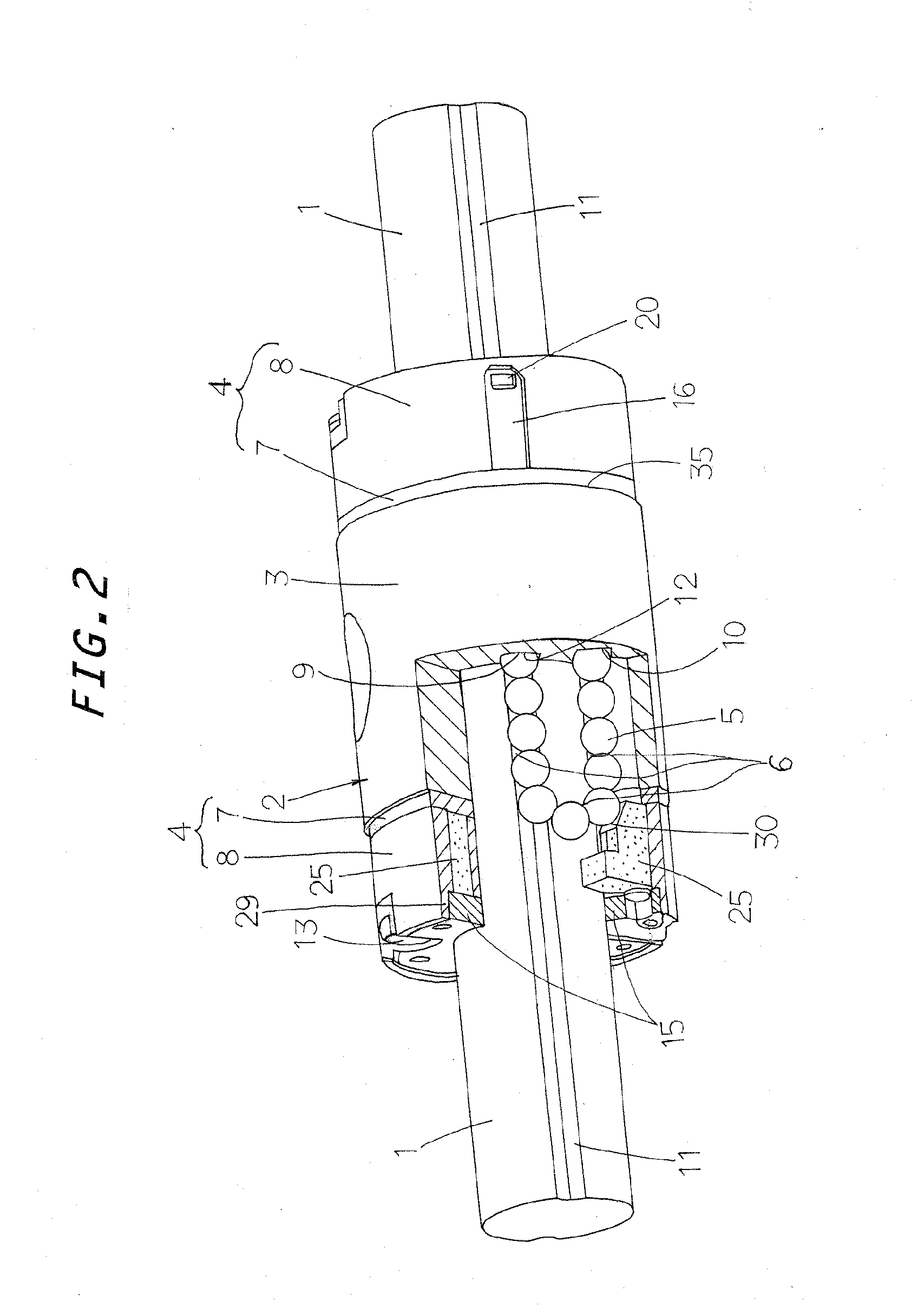
[0019]In the present invention, a miniature linear motion guide unit with lubrication
system disclosed in which the
carriage when viewed on the end surface thereof has the raceway grooves at two locations spaced diametrically opposite to each other, and the return passages
lying in line symmetry with respect to a line
lying midway between the raceway grooves, thereby making it possible to use the same end caps on either of the opposite ends surface of the
carriage to complete the slider.
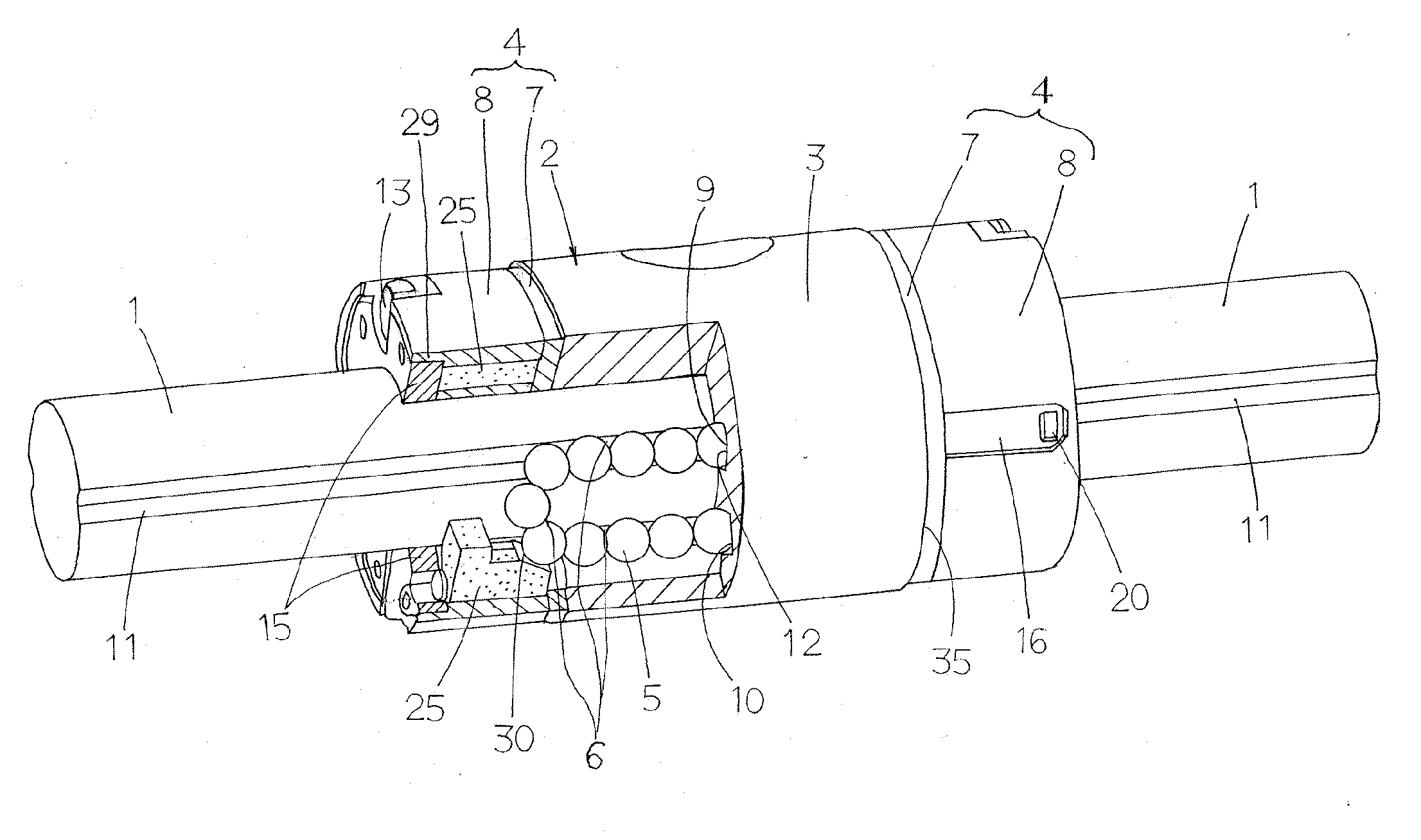
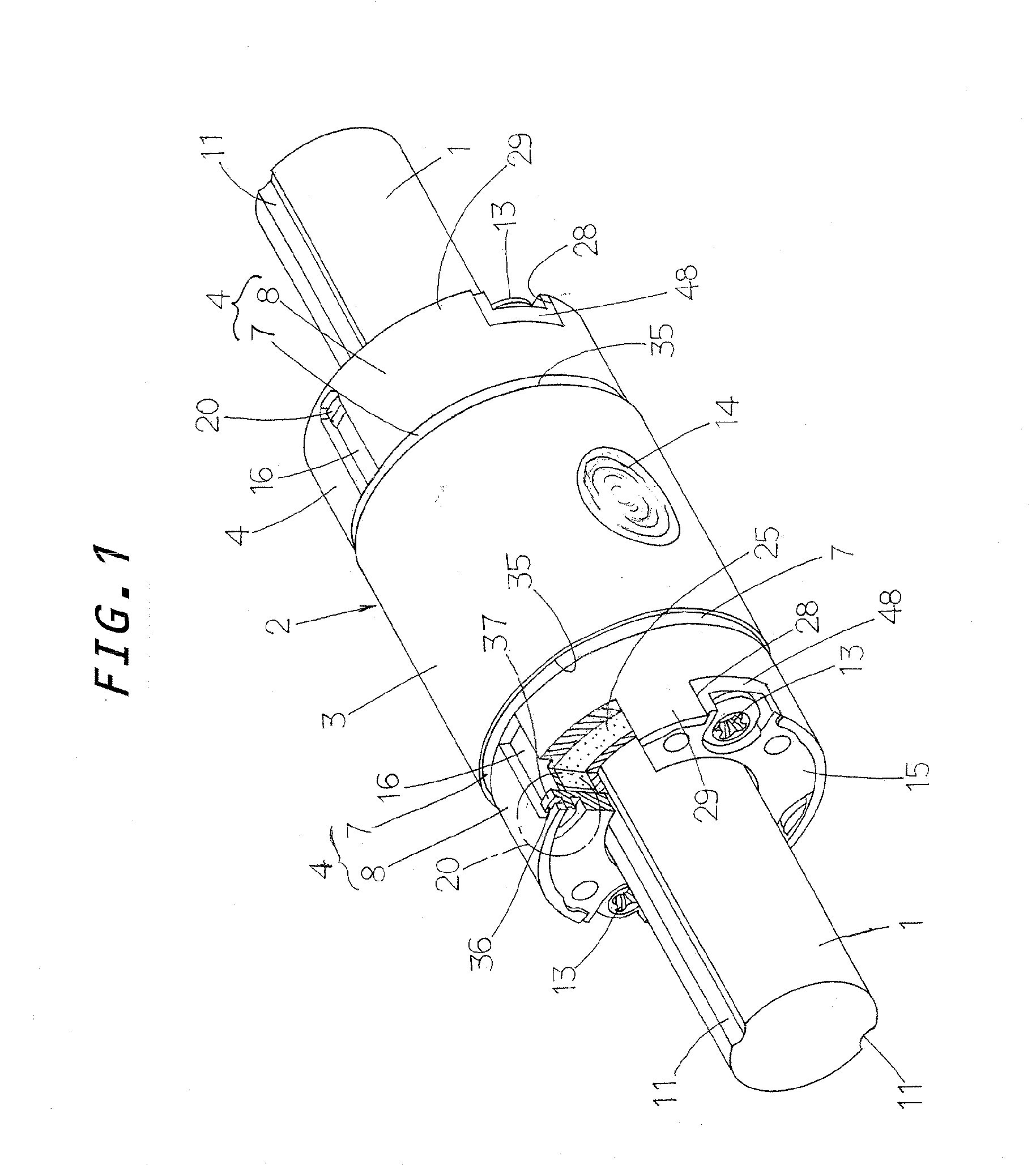
[0020]With the linear motion guide unit constructed as stated earlier, the lubricant applicator capable of preserving therein a desired amount of lubricant is received in the recess concaved below the outward end surface of the end cap. The lubricant applicator is made of a porous or open-cellular compact impregnated with the lubricant. Moreover, the retainer plate is applied on the outward end surface of the end cap to squeeze and seal the lubricant applicator inside the end cap, and kept in place with the snap-fit engagement with the end cap. Thus, various miniature parts are easily assembled with accuracy in a unitary full complement end cap which is in turn incorporated with the carriage to complete the slider.
[0021]With the linear motion guide unit of the present invention, even if the slider is so more miniature or downsized as to fit over the guide shaft not more than 6 mm, for example 4 mm in
diameter, the lubricant applicator impregnated with adequate amount of lubricant can be installed in the end cap and sealed with the retainer plate. With the linear motion guide unit constructed as stated earlier, moreover, the lug
lying around the retainer plate is first brought into the recess in the circular edge of the end cap to keep in place the retainer plate circumferentially of the end cap. Then, the retainer plate is forced deep in the recess in the end cap to get the locking
nose of the retainer plate snapping into the locking recess, thereby keeping axially in place the retainer plate relative to the end cap to secure the retainer plate to the end cap. Thus, the lubricant applicator may be set and sealed easily and certainly inside the end cap to provide the
ball spline virtually maintenance-free for lubrication.
[0022]As the end cap and the retainer plate are both made of synthetic resins, the locking
nose despite being very small or tiny in size is deformable elastically so as to easily snap into the locking
nose to make snap-fit engagement between the retainer plate and the end cap. Further, the presser pawls on the retainer plate squeeze elastically the lubricant applicator to fasten positively the lubricant applicator, thereby facilitating and simplifying the
assembly of the lubricant applicator and the retainer plate inside the end cap with keeping accurate matching with each other. With the linear motion guide unit of the present invention, the end cap major body has the apertures to accommodate the lubricant reservoir of the lubricant applicator. Thus, whether the lubricant applicator is surely installed in the end cap major body can be visible at a glance by only looking in at the apertures from the backside of the end cap major body and, therefore no installation of the lubricant applicator will be prevented before the completion of
assembly.

