Blade channel having an end wall contour and a turbomachine

a turbomachine and end wall technology, applied in the direction of propellers, water acting propulsive elements, air transportation, etc., can solve problems such as pressure loss, and achieve the effect of reducing secondary flow and improving efficiency

Active Publication Date: 2012-08-09
MTU AERO ENGINES GMBH
View PDF2 Cites 56 Cited by
  • Summary
  • Abstract
  • Description
  • Claims
  • Application Information

AI Technical Summary

Benefits of technology

[0005]It is an object of the present invention to provide a blade channel having an end wall contour in a turbomachine having a reduced secondary flow, as well as a turbomachine having an improved efficiency.
[0007]A blade channel according to the present invention having an end wall contour in a turbomachine is delimited by a pressure-side wall of a first blade in the circumferential direction and by an opposite suction-side wall of an adjoining second blade. In the radial direction, the blade channel is delimited by two opposite boundary walls, at least one of the boundary walls having at least one pressure-side elevation in the area of the pressure-side blade wall. According to the present invention, at least two suction-side recesses and at least one suction-side elevation are provided on the elevation-side boundary wall in the area of the suction-side blade wall, the suction-side elevation being situated between the recesses, viewed in the flow direction. As a result of the end wall contour, which is not axially symmetric according to the present invention, a static pressure field is influenced on the at least one boundary wall and on the blade walls in the boundary area in such a way that a secondary flow is reduced, thus reducing the flow losses and improving a flow toward a downstream blade cascade.
[0008]The elevations and recesses are preferably implemented locally and at a distance from one another. As a result, not-contoured boundary wall sections between the elevations and the recesses are formed, thus positively influencing the flow characteristics.
[0014]A turbomachine according to the present invention has at least one blade cascade having a plurality of blade channels according to the present invention. As a result of the reduced secondary flow and channel eddies, a turbomachine of this type distinguishes itself by an improved efficiency.

Problems solved by technology

Since the flow layers adjacent to the wall are deflected due to their lower speed to a greater extent than the flow layers at a distance from the wall, a secondary flow is formed which is superimposed on a main flow, thus resulting in pressure losses, among other things.

Method used


Image

  • Blade channel having an end wall contour and a turbomachine
  • Blade channel having an end wall contour and a turbomachine
  • Blade channel having an end wall contour and a turbomachine

Examples


Embodiment Construction

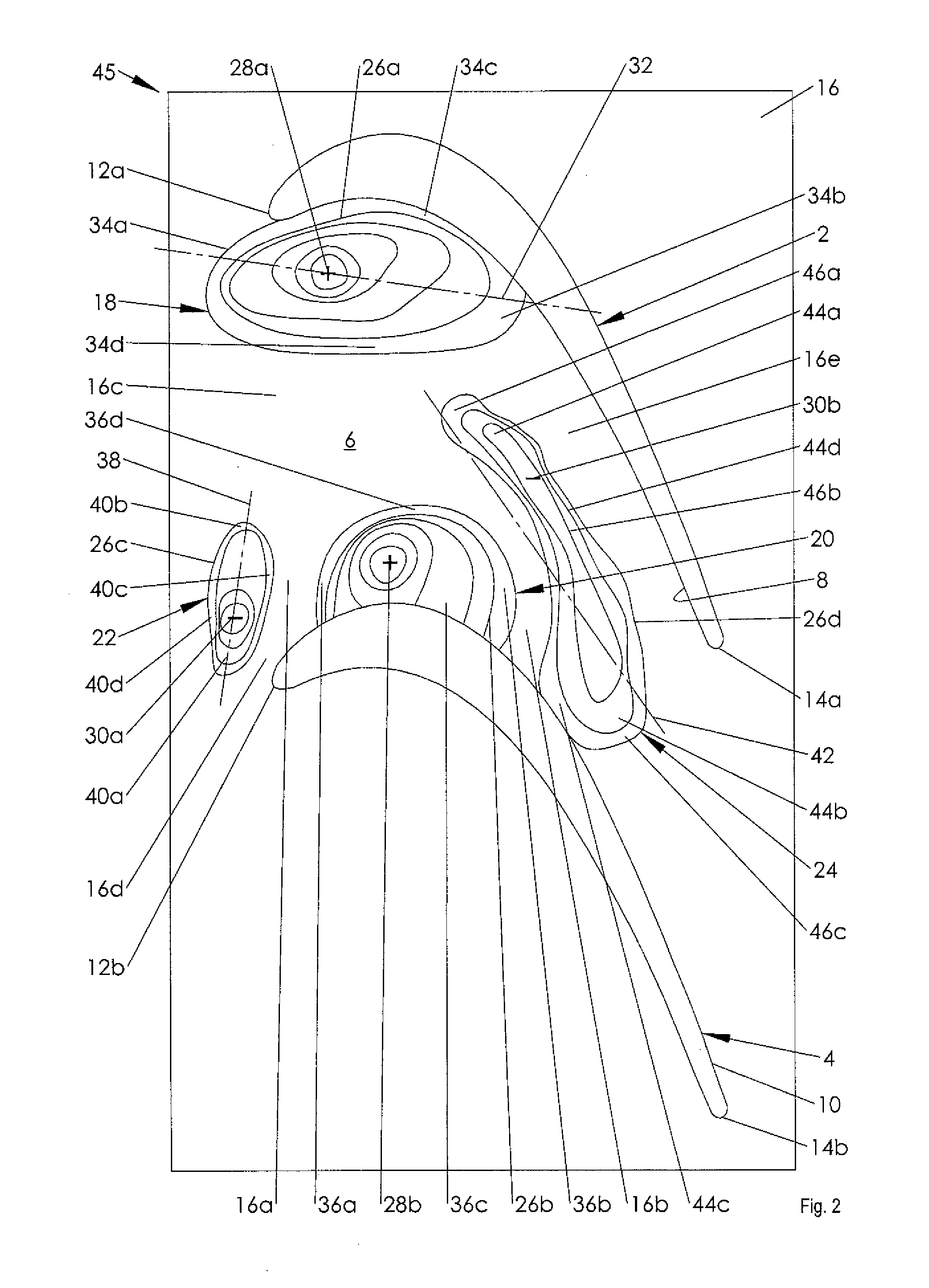
[0020]The two exemplary embodiments are each elucidated based on a blade cascade of an axial low-pressure turbine. The present invention is, however, also used for compressor rows or turbine rows in radial and diagonal designs

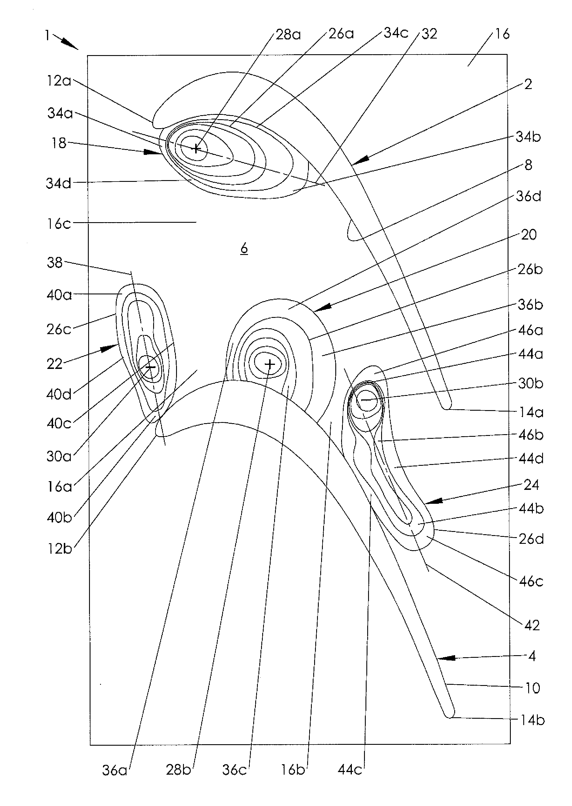
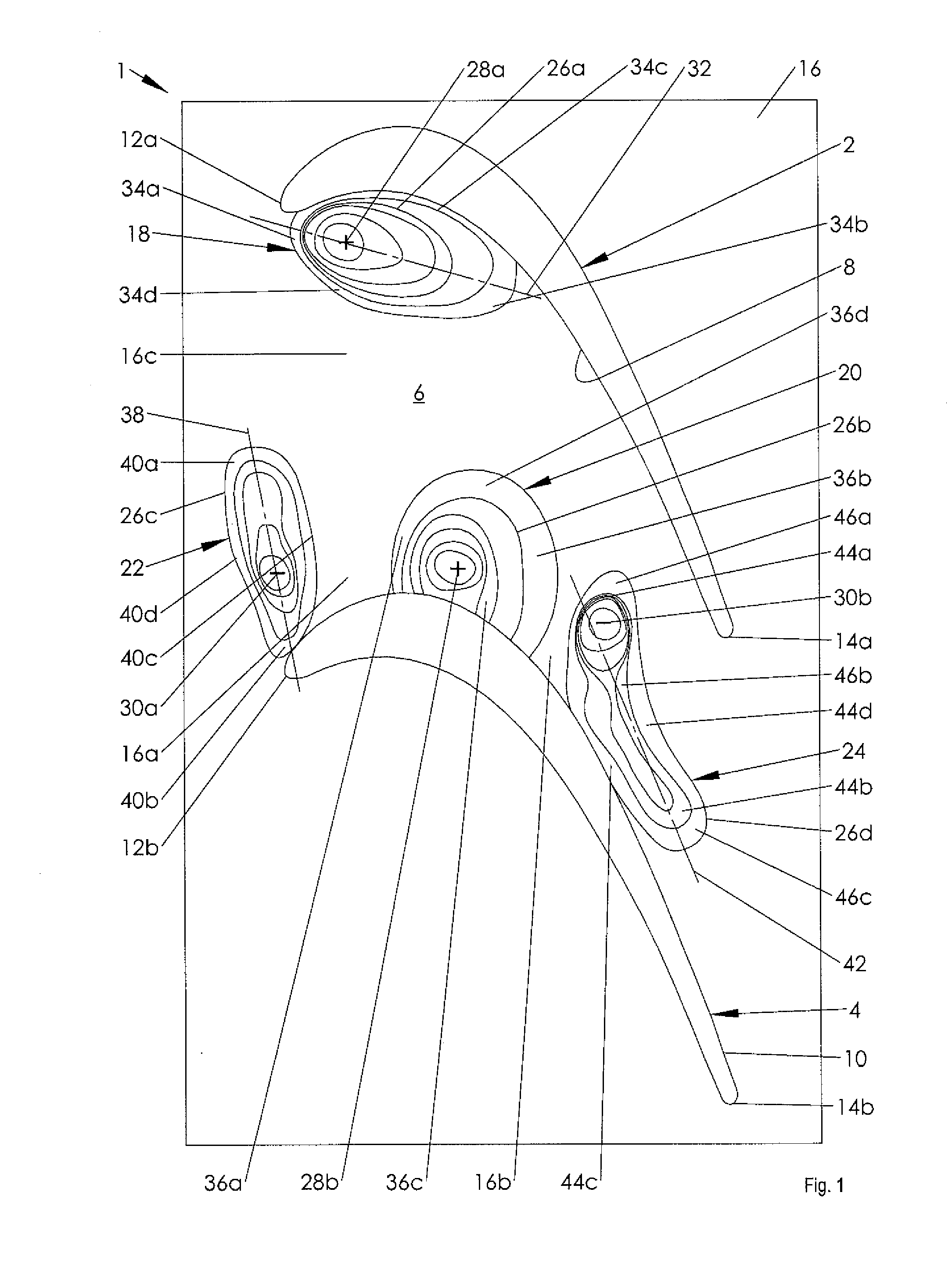
[0021]FIG. 1 shows a top view of a sectional illustration of a circumferential section, which is angled in a plane, of a first low-pressure-turbine-side blade cascade 1 according to the present invention of an axial turbomachine 100 (FIG. 3), such as a stationary gas turbine or a jet engine.

[0022]Blade cascade 1 has a plurality of blades 2, 4 which are situated adjacently to one another in the circumferential direction and each delimit a blade channel 6 in which a main flow is formed. In the circumferential direction, blade channel 6 is formed by a pressure-side wall 8 of first blade 2 and by an opposite suction-side wall 10 of second blade 4, each of which extends between a front edge 12a, 12b and a rear edge 14a, 14b of blades 2, 4. In the radial direction, b...


PUM


Abstract

A blade channel having a not-axially-symmetric end wall contour in a turbomachine is disclosed, the end wall contour having at least one individual contour in the form of an elevation, on the pressure side, and at least three individual contours in the form of two recesses and one elevation, on the suction side, the elevation being situated between the recesses in the flow direction; a turbomachine having a plurality of blade channels of this type is also disclosed.

Description

[0001]This claims the benefit of European Patent Application EP 11 153 627.2, filed Feb. 8, 2011, and hereby incorporated by reference herein.[0002]The present invention relates to a blade channel having an end wall contour in a turbomachine, and a turbomachine having blade channels of this type.BACKGROUND[0003]A fluid flow guided through a flow channel is deflected by a lateral pressure gradient in parallel to the end walls. Since the flow layers adjacent to the wall are deflected due to their lower speed to a greater extent than the flow layers at a distance from the wall, a secondary flow is formed which is superimposed on a main flow, thus resulting in pressure losses, among other things. Secondary flows of this type regularly occur in blade cascades of turbomachines, such as gas and steam turbines. The blade cascades include a plurality of blades or vanes which are situated next to one another in the circumferential direction and which are situated in a rotary-symmetric flow ch...

Claims


Application Information

Patent Timeline
Patent Type & Authority Applications(United States)
IPC IPC(8): F01D5/14
CPCF01D5/143Y02T50/673F01D5/145Y02T50/60
Inventor MAHLE, INGANIEBLER, MICHAELA
Owner MTU AERO ENGINES GMBH
Why Eureka
Try Eureka