

Minimally Invasive Implant and Method
- Summary
- Abstract
- Description
- Claims
- Application Information
AI Technical Summary
Benefits of technology
Problems solved by technology
Method used
Image

Examples
Embodiment Construction
[0051]Referring generally to FIGS. 1-41, like reference numerals can designate identical, similar or corresponding parts throughout the views. The following description is meant to be illustrative only, and not limiting other embodiments of this invention that will be apparent to those of ordinary skill in the art in view of this description.
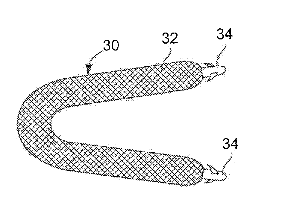
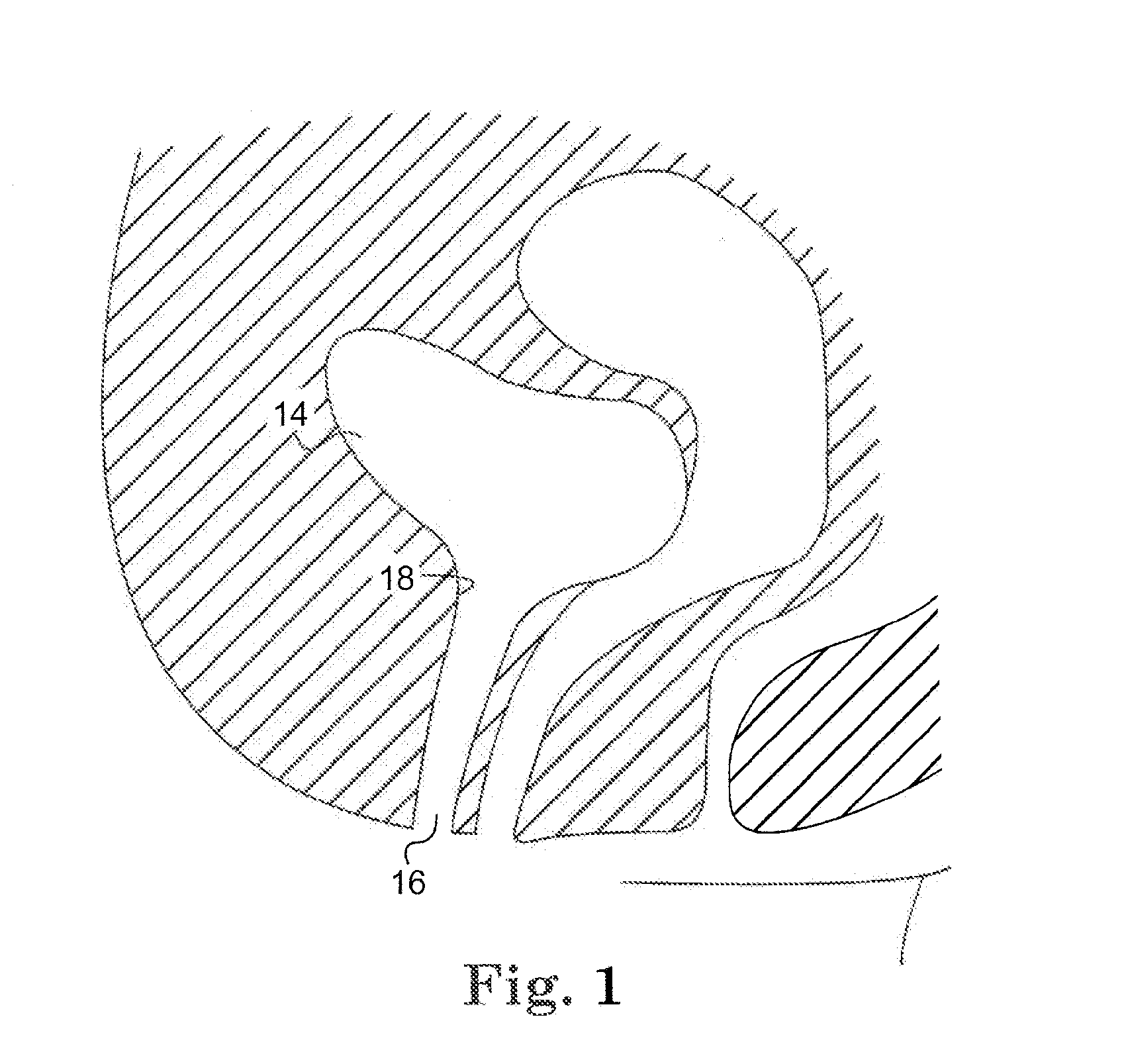
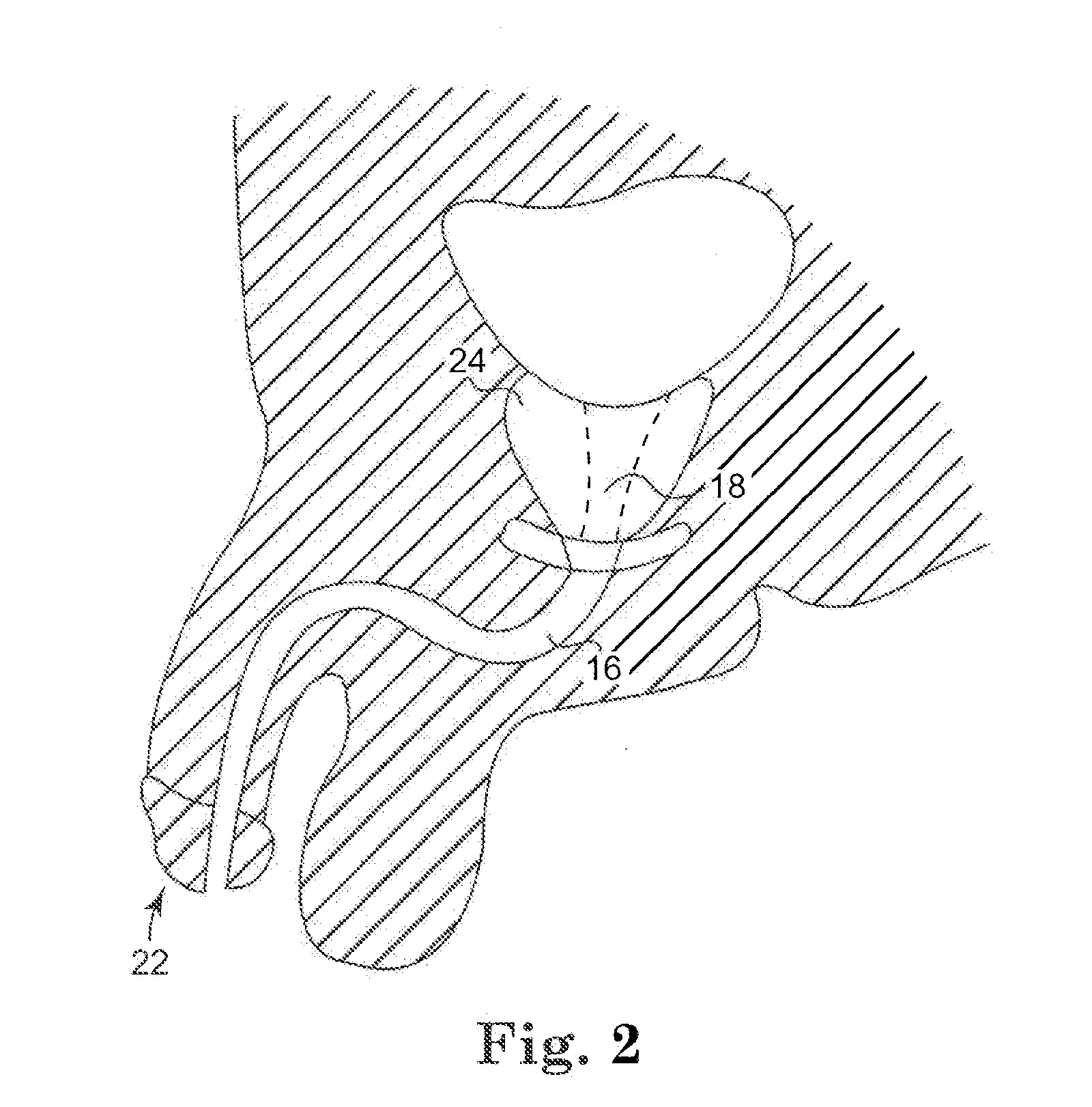
[0052]One aspect of the present invention is an apparatus and method of treating urinary incontinence in males or females. In various embodiments, one or more implants or implant members are placed in strategically located positions to pull up or otherwise tighten tissue and / or muscle lateral to the urethra to generally re-establish the original anatomical structure of the patient. Various systems, devices, structures, techniques and methods, alone or in combination, as disclosed in U.S. Patent Publication Nos. U.S. Pat. Nos. 6,911,003, 6,612,977, 6,802,807, 2002 / 0161382, 2004 / 0039453 and 2008 / 0045782, and International PCT Publication No. 2008 / ...
PUM
 Abstract
Description
Claims
Application Information