
Wearable Vital Signs Monitor

a monitor and vital signs technology, applied in the field of physiological monitors, can solve the problems of multiple expensive specialized devices, inconvenient home use, expensive equipment rental, etc., and achieve the effect of reducing interference signals

Inactive Publication Date: 2012-08-09
ROBERT F DUDLEY AS TRUSTEE OF THE QUANTTUS LIQUIDATING TRUST +1
View PDF15 Cites 151 Cited by
  • Summary
  • Abstract
  • Description
  • Claims
  • Application Information

AI Technical Summary

Benefits of technology

[0007]In yet another embodiment, the electronic module further includes a display module for providing information to a user in response to measured and calculated vital signs. In one embodiment, the display module provides information to the user in response to measured and calculated vital signs that are out of acceptable range. In one embodiment, the display module provides auditory information. In another embodiment, the electronic module further comprises a memory module for saving recorded data. In yet another embodiment, the electronic module further comprises a wireless communication module for sending data to a base-station. In still another embodiment, the base-station provides feedback to a user in response to measured and calculated vital signs. In yet another embodiment, the base-station provides information to a user in response to measured and calculated vital signs that are out of acceptable range. In yet another embodiment, the base-station controls the operation of the electronic module based on measured and calculated vital signs. In still yet another embodiment, the processor performs, in response to one or more of the ECG signal, the BCG signal, the PPG signal, and the acceleration data, error detection for one or more of the heart rate, the respiratory rate, and the blood pressure. In another embodiment, the monitor further includes a switch the processor uses for turning on and off the BCG and the PPG modules in response to the ECG data, to reduce power consumption. In yet another embodiment, the monitor further includes a switch the processor uses for turning on and off the PPG module in response to the BCG data, to reduce power consumption. In still yet another embodiment, the monitor includes a switch the processor uses for turning on and off the ECG, the BCG, or the PPG module in response to accelerometer data so as to reduce power consumption. In still another embodiment, the monitor calculates the blood pressure using cross-correlation of either the ECG and the BCG signals, or the ECG and the PPG signals. In another embodiment, the monitor calculates the heart rate using cross-correlation of two of the ECG, the BCG, and the PPG signals.
[0009]Another aspect of the invention relates to a BCG monitoring device. In one embodiment, the BCG monitoring device includes a housing sized and shaped for fitting adjacent the ear of a wearer and having two capacitive electrodes positioned in the mastoid region of the head of a wearer to sense head movements by transducing mechanical movements into electrical signals and a BCG module located within the housing. In another embodiment, the BCG monitor includes a differential signal amplifier having an output terminal and two input terminals, each input terminal in communication with a respective one of the capacitive electrodes and an analog-to-digital converter in communication with the output terminal of the differential signal amplifier. In yet another embodiment, the BCG monitoring device further includes a third electrode positioned at the mastoid region of the head of a wearer to reduce common mode interference signals.
[0011]Another aspect of the invention relates to an ECG monitoring device. In one embodiment, the ECG monitoring device includes a housing sized and shaped for fitting adjacent the ear of a wearer; two dry or gel-based electrodes positioned at the mastoid region of the head of a wearer to sense ECG signals and an ECG module located within the housing. In one embodiment, the ECG module includes a differential signal amplifier having an output terminal and two input terminals, each input terminal in communication with a respective one of the dry or gel-based electrodes; and an analog-to-digital converter in communication with the output terminal of the differential signal amplifier. In another embodiment, the ECG monitoring device further includes a third electrode positioned in the mastoid region of the head of a wearer to reduce common-mode interference signals. In yet another embodiment, the ECG monitoring device further includes a filter in communication with the output terminal of the differential amplifier to reduce interference signals.
[0014]Yet another aspect of the invention relates to another method for monitoring BCG. In one embodiment, the method for measuring BCG includes the steps of positioning a housing containing an accelerometer that senses head movements and sized and shaped for fitting adjacent the ear of a user. In another embodiment, the BCG method further includes filtering the output of the accelerometer to reduce interference signals.

Problems solved by technology

To monitor vital signs, multiple expensive specialized devices typically are used in a controlled setting such as a hospital.
The bulk and costs of these devices make them inappropriate for home use.
Many times, this requires the renting of expensive equipment for long periods of time.
In addition, sensors for measuring different vital signs at home are bulky and difficult to wear while the wearer is performing his or her ordinary functions.

Method used


Image

  • Wearable Vital Signs Monitor
  • Wearable Vital Signs Monitor
  • Wearable Vital Signs Monitor

Examples


Embodiment Construction

[0031]The following description refers to the accompanying drawings that illustrate certain embodiments of the invention. Other embodiments are possible and modifications may be made to the embodiments without departing from the spirit and scope of the invention. Therefore, the following detailed description is not meant to limit the invention. Rather, the scope of the invention is defined by the appended claims.

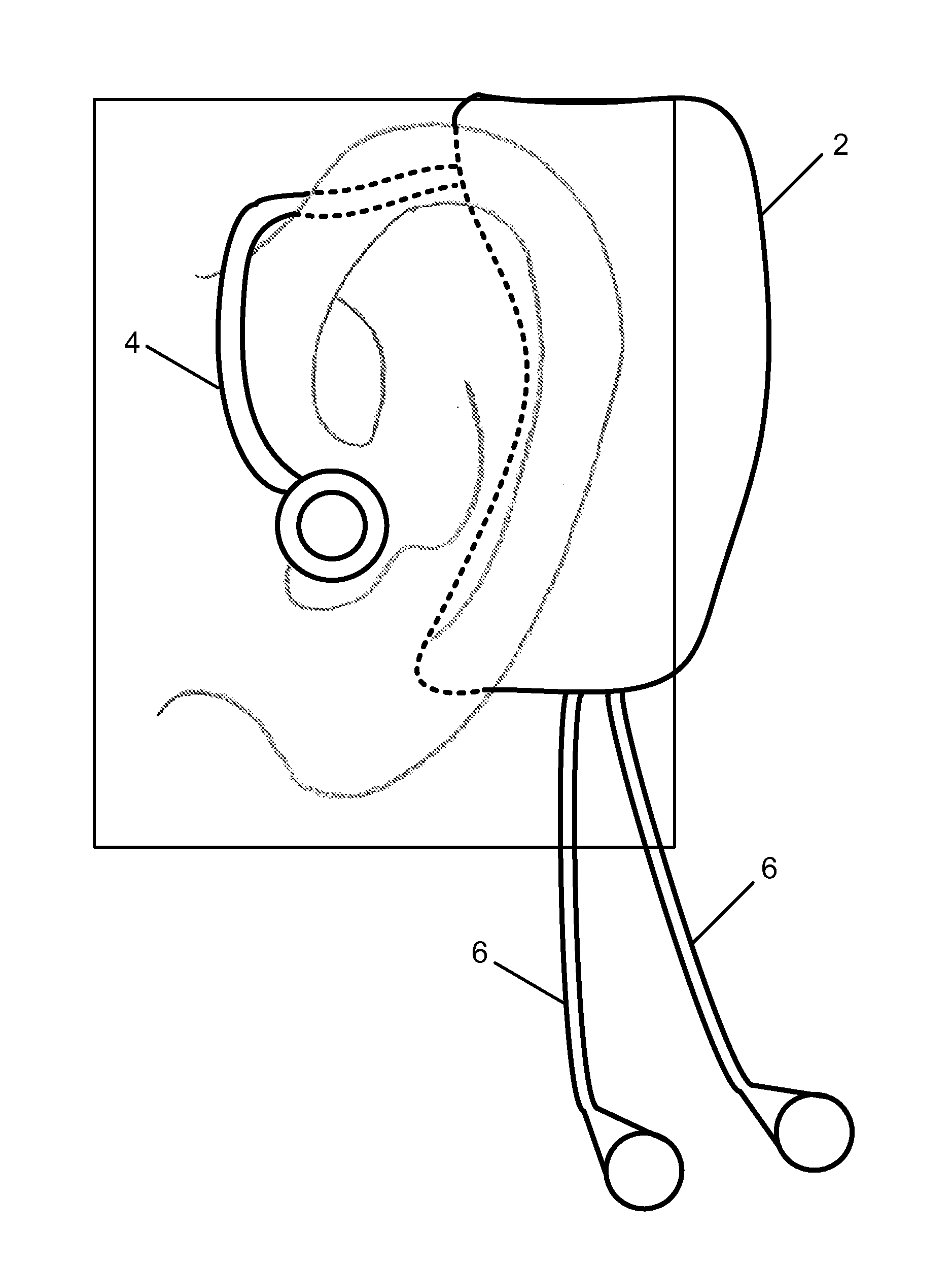
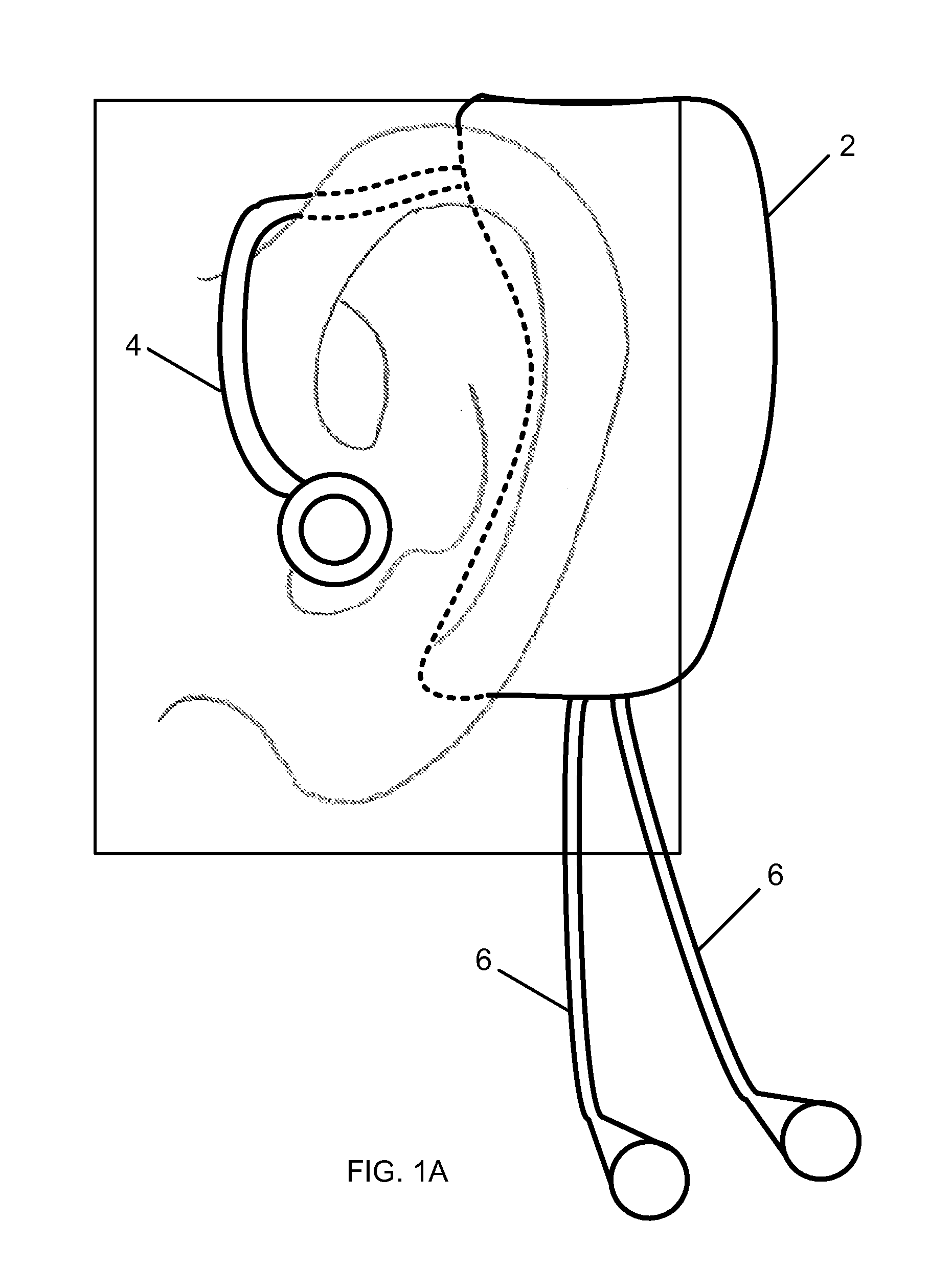
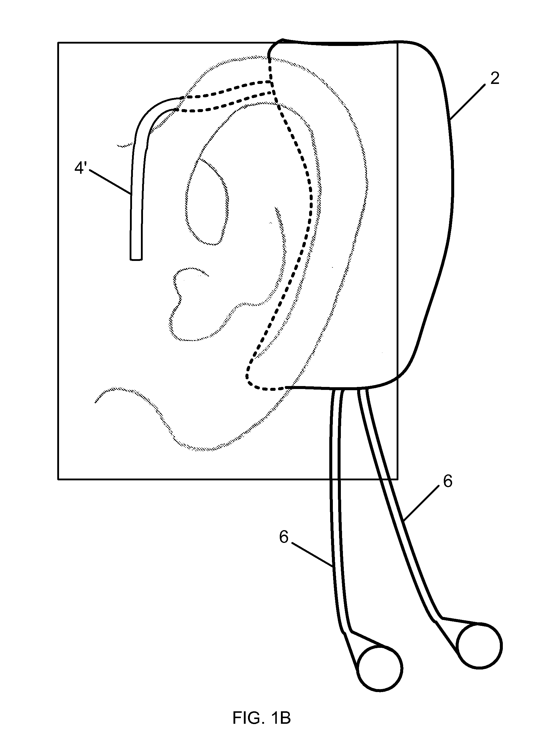
[0032]Referring to FIGS. 1a and b, in brief overview, two embodiments are depicted in which a device housing 2 fits behind the ear of a wearer, and is held in place by an earbud 4 located within the ear canal of the patient or by an earclip 4′ which fits over the ear of a wearer. In the embodiments shown, electrode leads 6 extend beyond the housing 2 and attach to electrodes mounted behind the ear of the wearer, near the wearer's mastoid. In another embodiment, the electrodes are built into the housing 2 and do not extend beyond the housing 2.

[0033]Referring to FIG. 2, the e...


PUM


Abstract

A method and monitor for monitoring vital signs. In one embodiment, the vital signs monitor includes a housing sized and shaped for fitting adjacent the ear of a wearer and an electronic module for measuring vital signs. The electronic module for measuring vital signs is located within the housing and includes a plurality of vital signs sensing modules in communication with a processor. The plurality of sensing modules includes at least two of the modules selected from the group of a ballistocardiographic (BCG) module, a photoplethysmographic (PPG) module, an accelerometer module, a temperature measurement module, and an electrocardiographic (ECG) module. In one embodiment, the processor calculates additional vital signs in response to signals from the plurality of vital signs sensing modules.

Description

FIELD OF INVENTION[0001]This invention relates to the field of physiological monitors and more specifically to a wearable device for measuring vital signs.BACKGROUND[0002]Monitoring vital signs is an important procedure in the caring for the elderly, sick and injured. Not only does the monitoring provide diagnostic clues as to the cause of the wearer's illness but also provides an advance warning if the wearer's condition is worsening.[0003]In addition, healthy individuals frequently desire to measure certain vital signs as they exercise in order to track their physical condition both instantaneously and over time. Such monitors provide feedback to the user and help identify risks for certain diseases.[0004]To monitor vital signs, multiple expensive specialized devices typically are used in a controlled setting such as a hospital. The bulk and costs of these devices make them inappropriate for home use. However, to reduce healthcare costs and to help the patient recover more quickly...

Claims


Application Information

Patent Timeline
Patent Type & Authority Applications(United States)
IPC IPC(8): A61B5/0205A61B5/0408A61B5/1455A61B5/332
CPCA61B5/01A61B5/02055A61B5/02125A61B5/02416A61B5/02438A61B5/029A61B2562/0219A61B5/0816A61B5/11A61B5/1102A61B5/14551A61B5/6815A61B2560/0209A61B5/0402A61B5/318
Inventor HE, DAVID DAWINOKUR, ERIC S.SODINI, CHARLES G.
Owner ROBERT F DUDLEY AS TRUSTEE OF THE QUANTTUS LIQUIDATING TRUST
Learn More