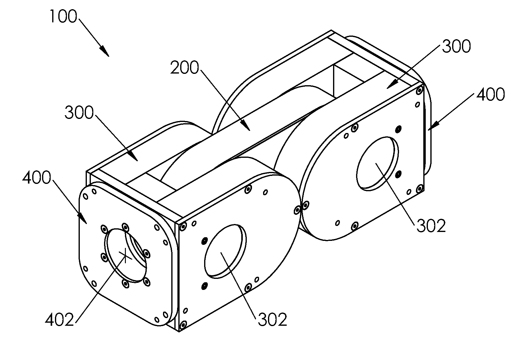
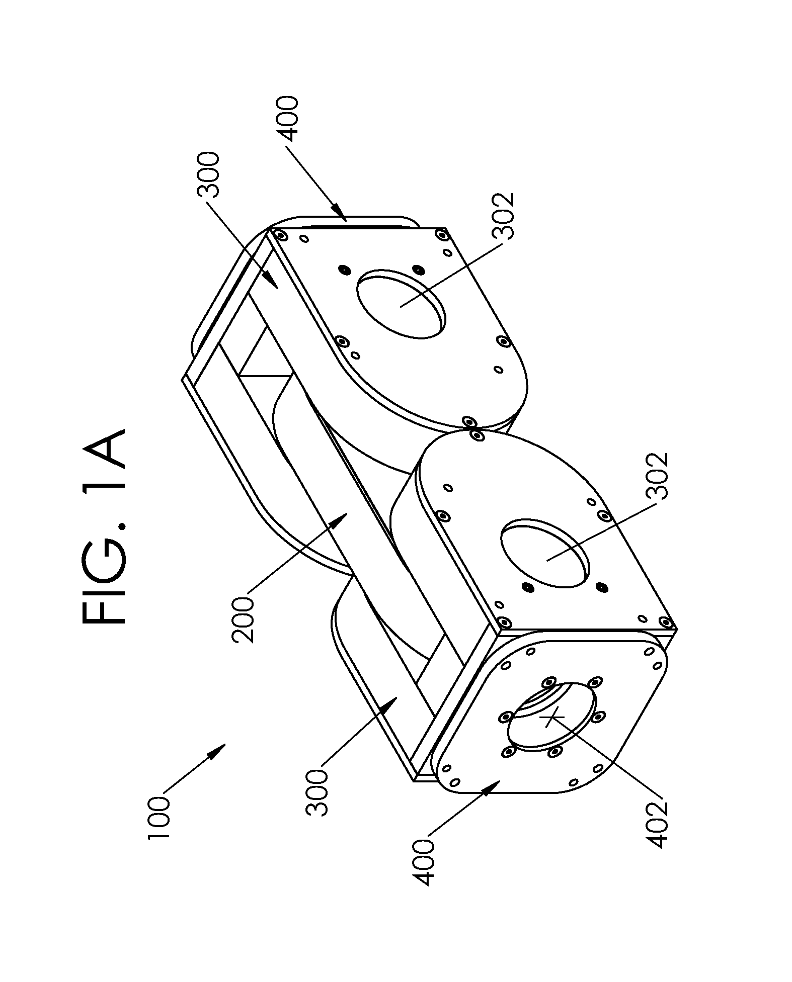
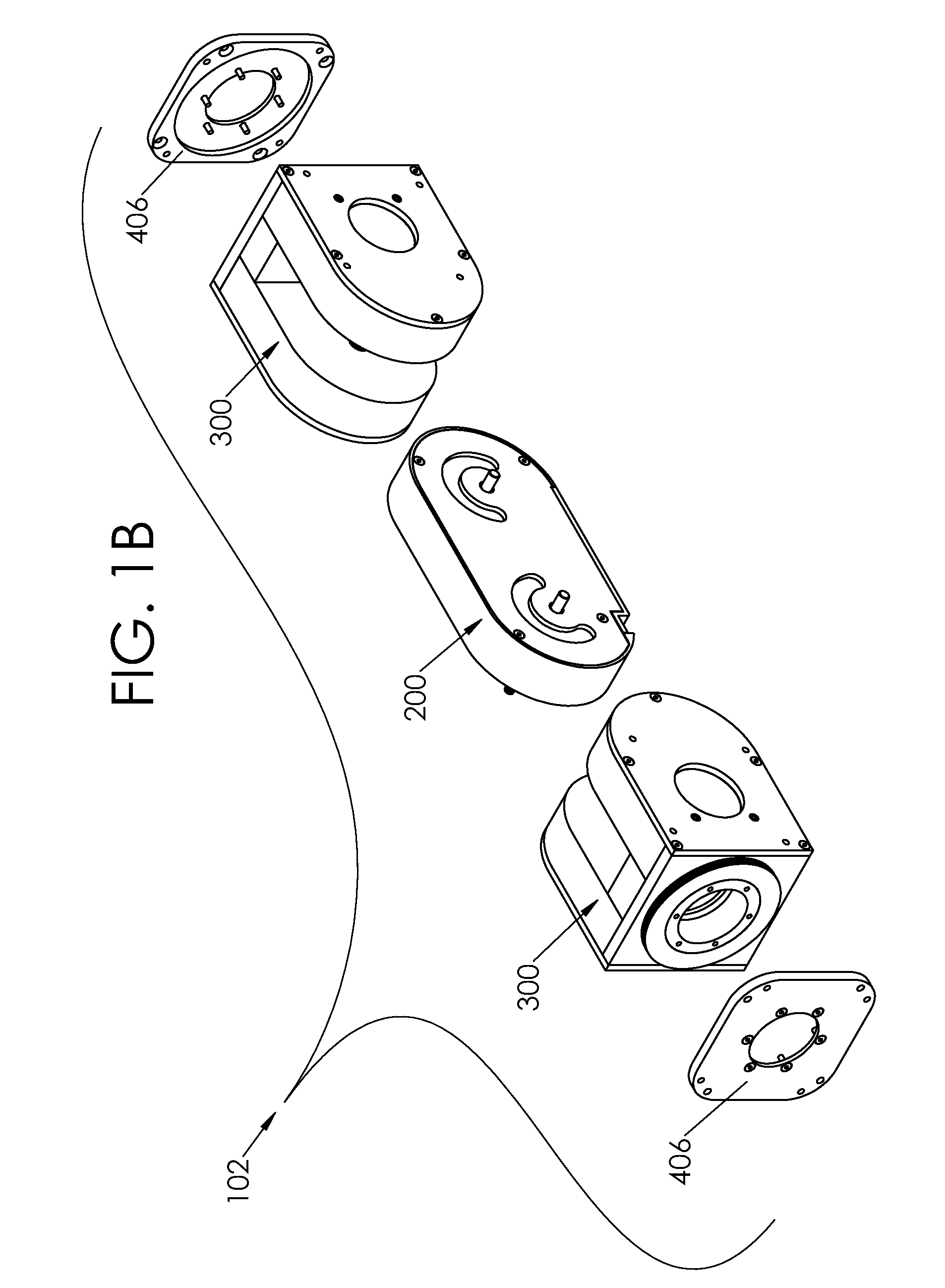
Four degree of freedom (4-dof) single modular robot unit or joint
a robot and modular technology, applied in the field of robotics, can solve the problems of high part count and programming complexity, and achieve the effect of high number of degrees of freedom
- Summary
- Abstract
- Description
- Claims
- Application Information
AI Technical Summary
Benefits of technology
Problems solved by technology
Method used
Image

Examples
embodiment 1
[0167]2. The module of embodiment 1, wherein the faceplate rotates about the outer link about a faceplate rotation axis.
[0168]3. The module of embodiment 1, wherein the outer link is pivotably connected to the center link through a pivot shaft disposed between the outer link and the center link.
embodiment 3
[0169]4. The module of embodiment 3, wherein the pivot shaft has a pivot axis about which the center link pivots relative to the outer link.
[0170]5. The module of embodiment 1, further comprising a faceplate assembly, said faceplate assembly comprising: a frame connected to the outer link; said faceplate rotationally connected to the frame; wherein the faceplate rotates about the outer link about a faceplate rotation axis.
[0171]6. The module of embodiment 1, wherein one of the center links is pivotably connected to two of the outer links.
embodiment 6
[0172]7. The module of embodiment 6, wherein the outer links are pivotably connected to the center link through two pivot shafts.
[0173]8. The module of embodiment 1, further comprising a modular robot unit, said modular robot unit comprising at least two outer links interconnected by their respective faceplates.
PUM
 Abstract
Description
Claims
Application Information
 - Generate Ideas
- Intellectual Property
- Life Sciences
- Materials
- Tech Scout
- Unparalleled Data Quality
- Higher Quality Content
- 60% Fewer Hallucinations
Browse by: Latest US Patents, China's latest patents, Technical Efficacy Thesaurus, Application Domain, Technology Topic, Popular Technical Reports.
© 2025 PatSnap. All rights reserved.Legal|Privacy policy|Modern Slavery Act Transparency Statement|Sitemap|About US| Contact US: help@patsnap.com