Electric power steering system

Inactive Publication Date: 2012-08-16
JTEKT CORP
View PDF4 Cites 6 Cited by
  • Summary
  • Abstract
  • Description
  • Claims
  • Application Information

AI Technical Summary

Benefits of technology

[0009]It is an object of the invention to provide an electric power steering system capable of minimizing the difference betwe

Problems solved by technology

The electric power steering system described in Japanese Patent Application Publication No. 2004-66999, however, does not address this issue.
Therefore, there is a possibility of a large difference between the motor resistance actually measured and st

Method used


Image

  • Electric power steering system
  • Electric power steering system
  • Electric power steering system

Examples


Embodiment Construction

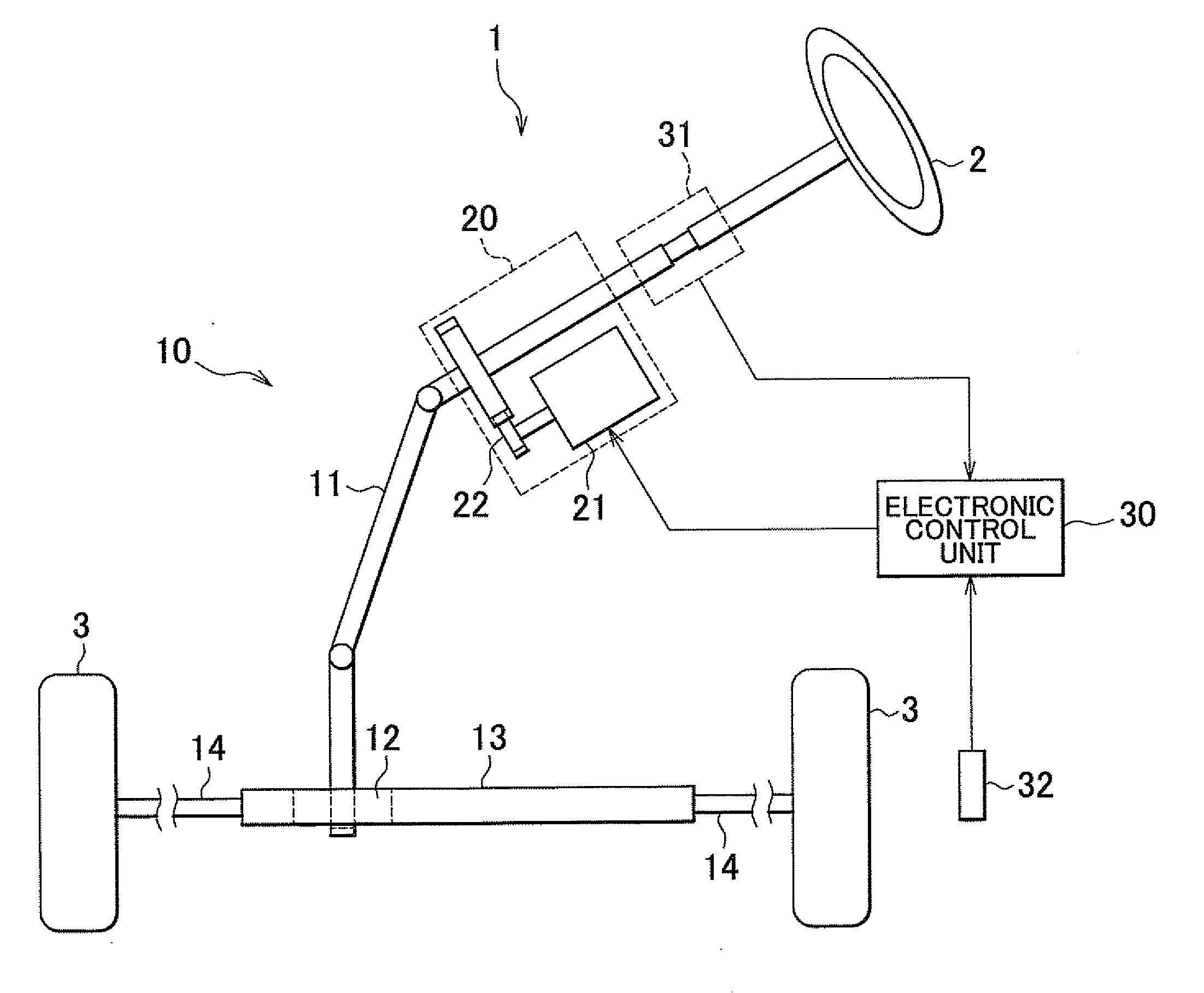
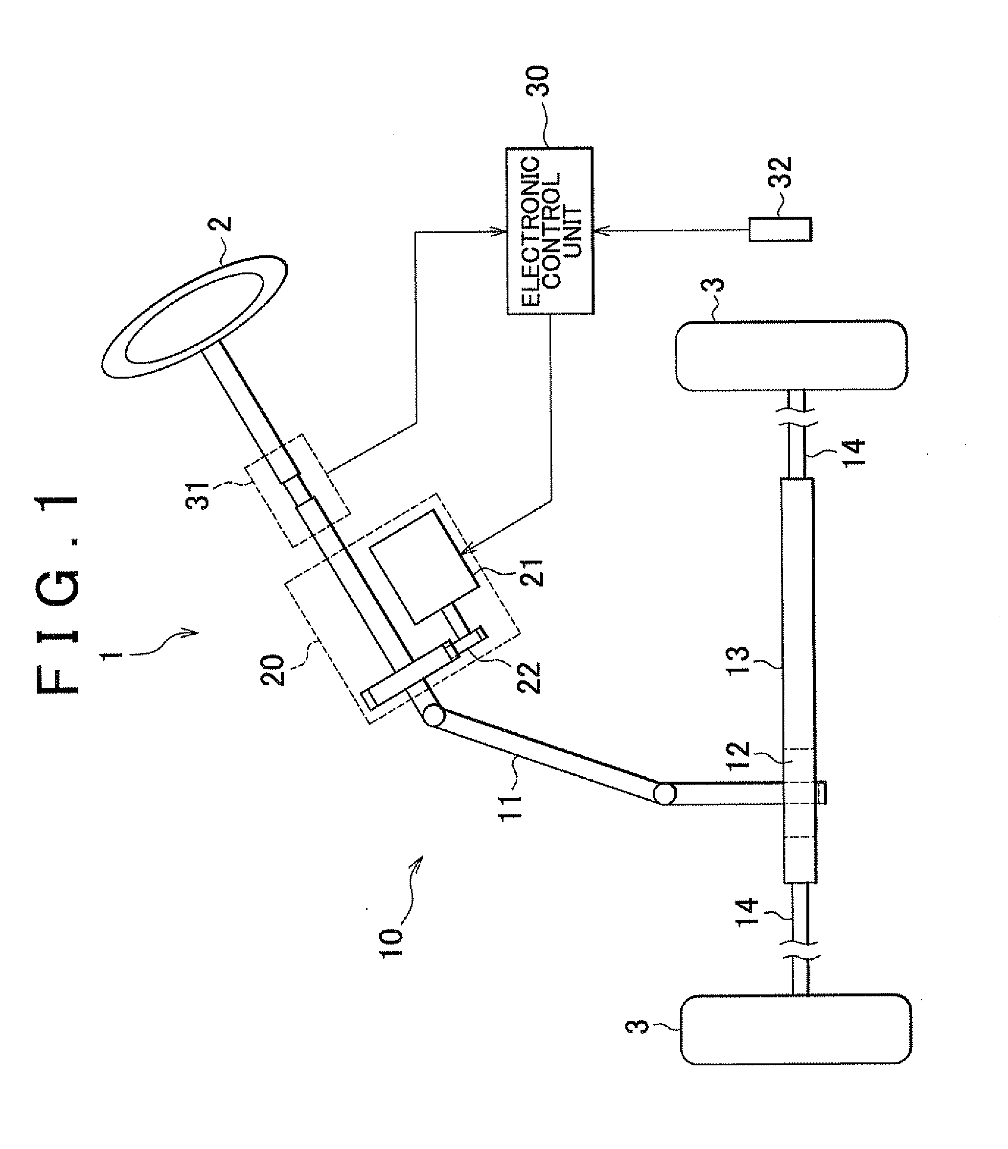
[0024]A first example embodiment of the invention will be described with reference to FIGS. 1 to 8. An electric power steering system 1 includes a steering angle transfer mechanism 10, an EPS actuator unit 20, and an electronic control unit 30. The steering angle transfer mechanism 10 transfers the rotation of a steering wheel 2 to steered wheels 3. The EPS actuator unit 20 applies, to the steering angle transfer mechanism 10, the force for assisting the manual operation of the steering wheel 2 (will hereinafter be referred to as “assist force”). The electronic control unit 30 controls the EPS actuator unit 20. Further, the electric power steering system 1 includes a plurality of sensors that detect the operation states of these devices.

[0025]The steering angle transfer mechanism 10 includes a steering shaft 11, a rack and pinion mechanism 12, a rack shaft 13, and tie rods 14. The steering shaft 11 rotates together with the steering wheel 2. The rack and pinion mechanism 12 transfer...


PUM


Abstract

An electric power steering system calculates a motor resistance Rm using a resistance map, and calculates an estimated inducted voltage based on a motor current and a motor voltage. If the estimated induced voltage is determined as being equal to or smaller than a determination value that is set in accordance with the current level, the electric power steering system calculates a motor resistance (estimated motor resistance Rma) and updates the resistance map based on the estimated motor resistance Rma.

Description

INCORPORATION BY REFERENCE[0001]The disclosures of Japanese Patent Applications No. 2011-028979 filed on Feb. 14, 2011 and No. 2011-227069 filed on Oct. 14, 2011 including the specifications, drawings and abstracts, are incorporated herein by reference in their entireties.BACKGROUND OF THE INVENTION[0002]1. Field of the Invention[0003]The invention relates to an electric power steering system including a motor that applies assist force to a steering system.[0004]2. Description of Related Art[0005]Japanese Patent Application Publication No. 2004-66999 describes an electric power steering system that calculates a motor rotational angular velocity ω using Equation A shown below.ω=(Vm−R×IM) / Ke  Equation A[0006]In Equation A above, Vm represents the voltage between terminals of a motor (inter-terminal voltage), R represents the resistance of the motor, Im represents the current of the motor, and Ke is an induced voltage coefficient (V·s / rad). The resistance of the motor is actually measu...

Claims


Application Information

Patent Timeline
IPC IPC(8): B62D6/04B62D5/04B62D6/00B62D119/00H02P29/00
CPCB62D5/04B62D5/046B62D5/0481
Inventor NIIMI, KOZOKARIATSUMARI, YUJI
Owner JTEKT CORP
Why Eureka
Try Eureka