
Device and method for converting direct current into alternate current

a technology of direct current and alternate current, applied in the direction of ac-dc conversion, electric variable regulation, instruments, etc., can solve the problems of inability to switch, increase the energy loss, and increase the energy loss of the diode, so as to eliminate the disturbance and cut the energy loss to the utmost exten

Inactive Publication Date: 2012-08-16
META SYST
View PDF15 Cites 20 Cited by
  • Summary
  • Abstract
  • Description
  • Claims
  • Application Information

AI Technical Summary

Benefits of technology

"The present invention provides a device and method for converting direct current into alternate current that can eliminate disturbances and minimize energy losses. The device includes a multilevel converter and a modulation unit with piloting means for pulse modulation based on the output current value. The method includes a piloting phase for unipolar or complementary modulation based on the output current value. The technical effects of the invention are a simple, cost-effective solution that allows for efficient and effective conversion of direct current into alternate current."

Problems solved by technology

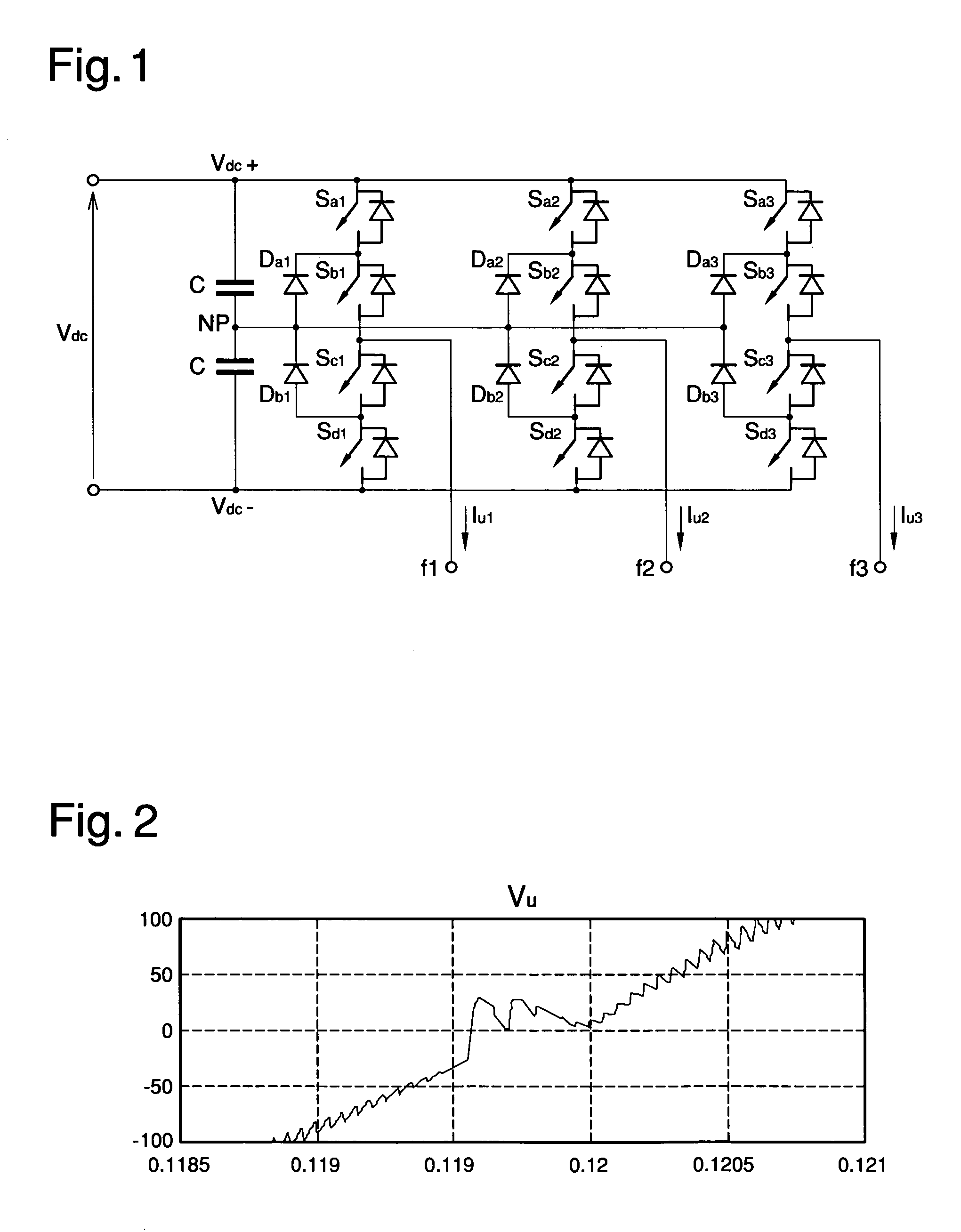
In particular, the central switches that switch at the switching frequency are not covered by current and, consequently, when the output current is not near the zero crossing numerous pointless switches are made.
This involves an inevitable increase in energy losses tied to the piloting circuit of the central switches of each branch and additional losses on the diodes tied to the respective dispersion currents.

Method used


Image

  • Device and method for converting direct current into alternate current
  • Device and method for converting direct current into alternate current
  • Device and method for converting direct current into alternate current

Examples


Embodiment Construction

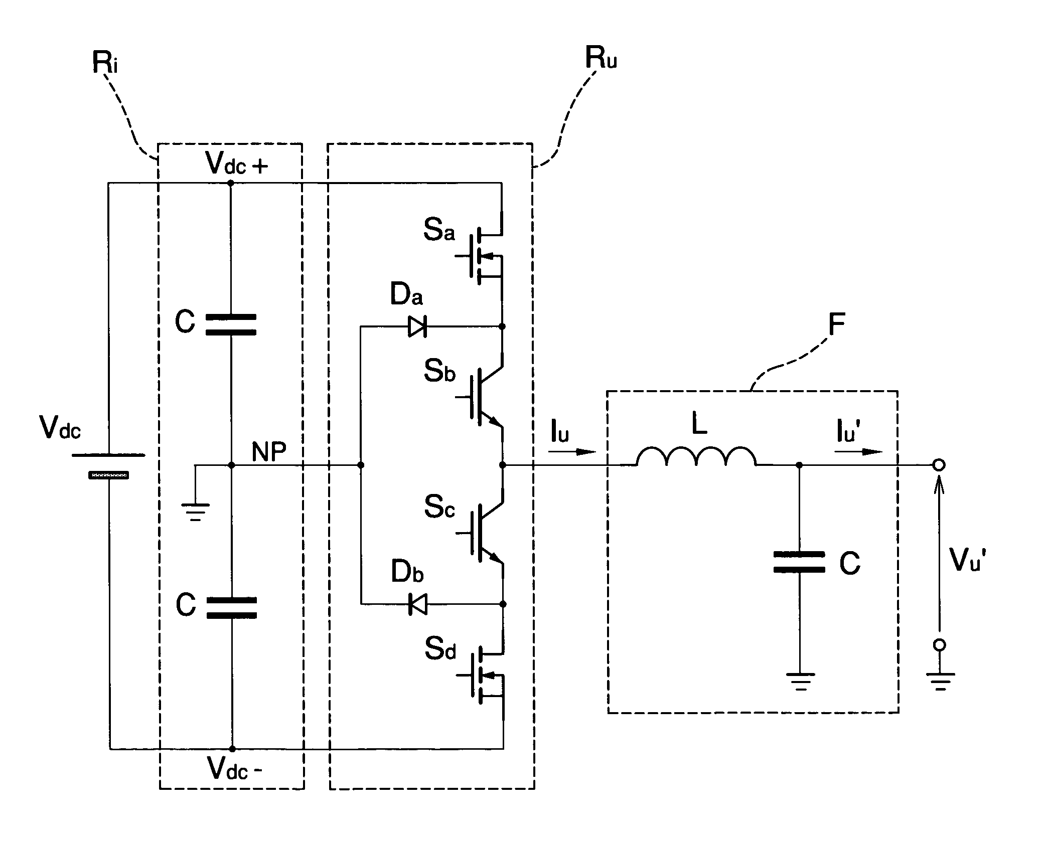
[0061]With particular reference to the figures from 5 to 14, globally indicated by D is a device for converting direct current into alternate current, of the type usable in numerous common-type applications such as, e.g., inside UPS units for the conversion of the direct current generated by a battery, for the conversion of the direct current produced by photovoltaic modules or, again, for regulating the speed of electric motors.

[0062]The device D, shown generally and schematically in FIG. 5, comprises a multi-level converter, of the type of an NPC (Neutral Point Clamped) converter or inverter, generically indicated by the reference CNPC.

[0063]The device D comprises a modulation unit, generically indicated in FIG. 5 with the reference M, which has means for piloting the converter CNPC for the conversion of a direct current Vdc entering the converter itself into an alternate output current Iu.

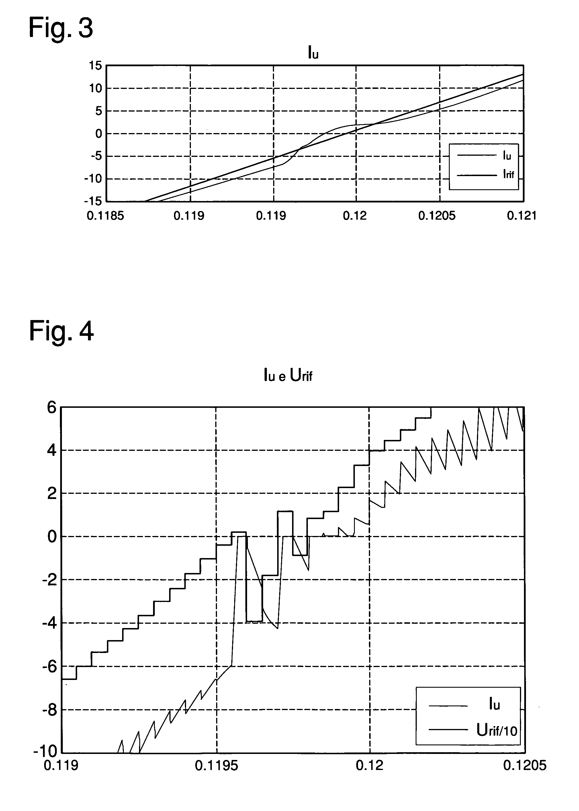
[0064]The device D also comprises a source suitable for generating a reference current Irif ...


PUM


Abstract

The device for converting direct current into alternate current comprises a multilevel converter associated with at least a source of direct current and a modulation unit having piloting means for piloting the converter for the conversion of the direct current into an alternate output current, in which the modulation unit comprises comparison means for comparing the output current value with a preset positive threshold value and a preset negative threshold value, the piloting means being suitable for piloting the converter with a pulse modulation of the unipolar type in the event of the output current value being above the positive threshold value or below the negative threshold value and with a pulse modulation of the complementary type in the event of the output current value being below the positive threshold value and above the negative threshold value. The method for converting direct current into alternate current comprises a piloting phase of a multilevel converter for the conversion of a direct voltage into an alternate output voltage, a comparison phase of the output current value with a preset positive threshold value and a preset negative threshold value, the piloting phase being suitable for piloting the converter with a pulse modulation of the unipolar type in the event of the output current value being above the positive threshold value or below the negative threshold value and with a pulse modulation of the complementary type in the event of the output current value being below the positive threshold value and above the negative threshold value.

Description

CROSS-REFERENCE TO RELATED APPLICATIONS[0001]This application is a national phase of PCT International Patent Application No PCT / IB2010 / 000640, filed Mar. 23, 2010, and Italian Patent Application No MO2009A000080, filed Mar. 31, 2009, in the Italian Patent Office, the disclosures of which are incorporated herein by reference.BACKGROUND OF THE INVENTION[0002]1. Field of the Invention[0003]The present invention relates to a device and method for converting direct current into alternate current.[0004]2. Description of the Related Art[0005]The use has been common and known for some time of electronic apparatus so-called “inverters” suitable for converting an input direct current into an output alternate current.[0006]The applications of the inverters are numerous and go, e.g., from the use in UPS units for the conversion of direct current from a supply battery to use in industry for regulating the speed of electric motors or, again, to use in industry to convert the electricity coming f...

Claims


Application Information

Patent Timeline
Patent Type & Authority Applications(United States)
IPC IPC(8): H02M7/44
CPCH02M7/487H02M7/5395
Inventor MALDINI, GIORGIOBUONOCUNTO, NICOLAPATSEVITCH, VLADISLAV
Owner META SYST
Learn More