
Motion detection device and method, video signal processing device and method and video display device

a technology of motion detection and video signal processing, applied in signal generators with optical-mechanical scanning, color television with bandwidth reduction, signal systems, etc., can solve problems such as detection errors, blurred edges, and ghosts, and achieve high accuracy and high quality

Active Publication Date: 2012-08-16
MITSUBISHI ELECTRIC CORP
View PDF6 Cites 38 Cited by
  • Summary
  • Abstract
  • Description
  • Claims
  • Application Information

AI Technical Summary

Benefits of technology

[0021]The invention provides another video signal processing device for performing three dimensional noise reduction based on the motion detection signal output by the above-mentioned motion detection device to eliminate noise components lacking frame-to-frame correlation from the video signal. This video signal processing device includes a motion adaptive noise reducer that uses the motion detection signal to control the noise reduction effect.
[0023]The motion detection device according to the invention can detect motion with high accuracy, so that still parts of the picture are not incorrectly detected as moving and moving parts are not incorrectly detected as still.
[0024]By using this motion detection result, the video signal processing devices according to the invention can perform motion adaptive processing without picture degradation due to flicker, blur, or combing.
[0025]By displaying a video signal processed by either of the above-mentioned video signal processing devices, the video display device according to the invention can display a video picture of high quality.

Problems solved by technology

When motion is present, however, trails and ghosts appear and edges become blurred.
When motion is detected only from frame-to-frame differences, however, detection errors occur.
There is still the problem, however, that the frame-to-frame differences do not just reflect motion; they also include a noise component.
Moreover, when there is a slowly moving object or a moving object with a repetitive pattern of vertical or horizontal lines, calculation of differences between filtered frames can fail to detect motion, causing the picture to be incorrectly classified as still, because the calculated differences may be very small.
Thus in a picture that is even slightly unsteady or includes noise, frame differences due to the unsteadiness or noise affect motion detection by causing still pictures to be misrecognized as moving, and in a picture with slowly moving objects or moving objects with repetitive patterns, filtering of the frame difference signal can make it impossible to obtain values from which motion can be detected, so that the motion fails to be recognized.
These motion detection errors lead to degraded picture quality by causing flicker, blur, combing, and other problems.
Combing is a problem in which the picture splits up in a comb-like pattern.

Method used


Image

  • Motion detection device and method, video signal processing device and method and video display device
  • Motion detection device and method, video signal processing device and method and video display device
  • Motion detection device and method, video signal processing device and method and video display device

Examples


first embodiment

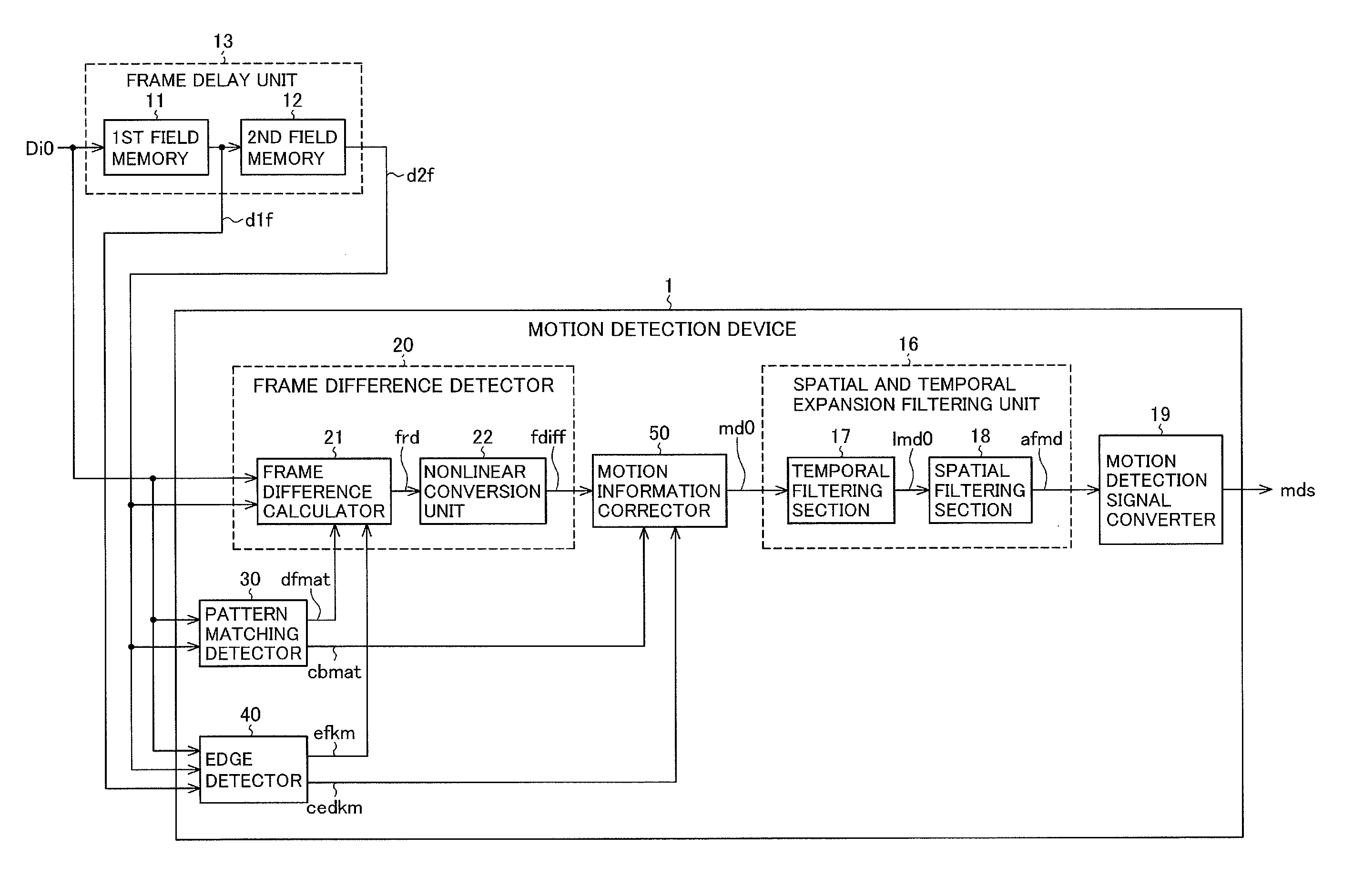
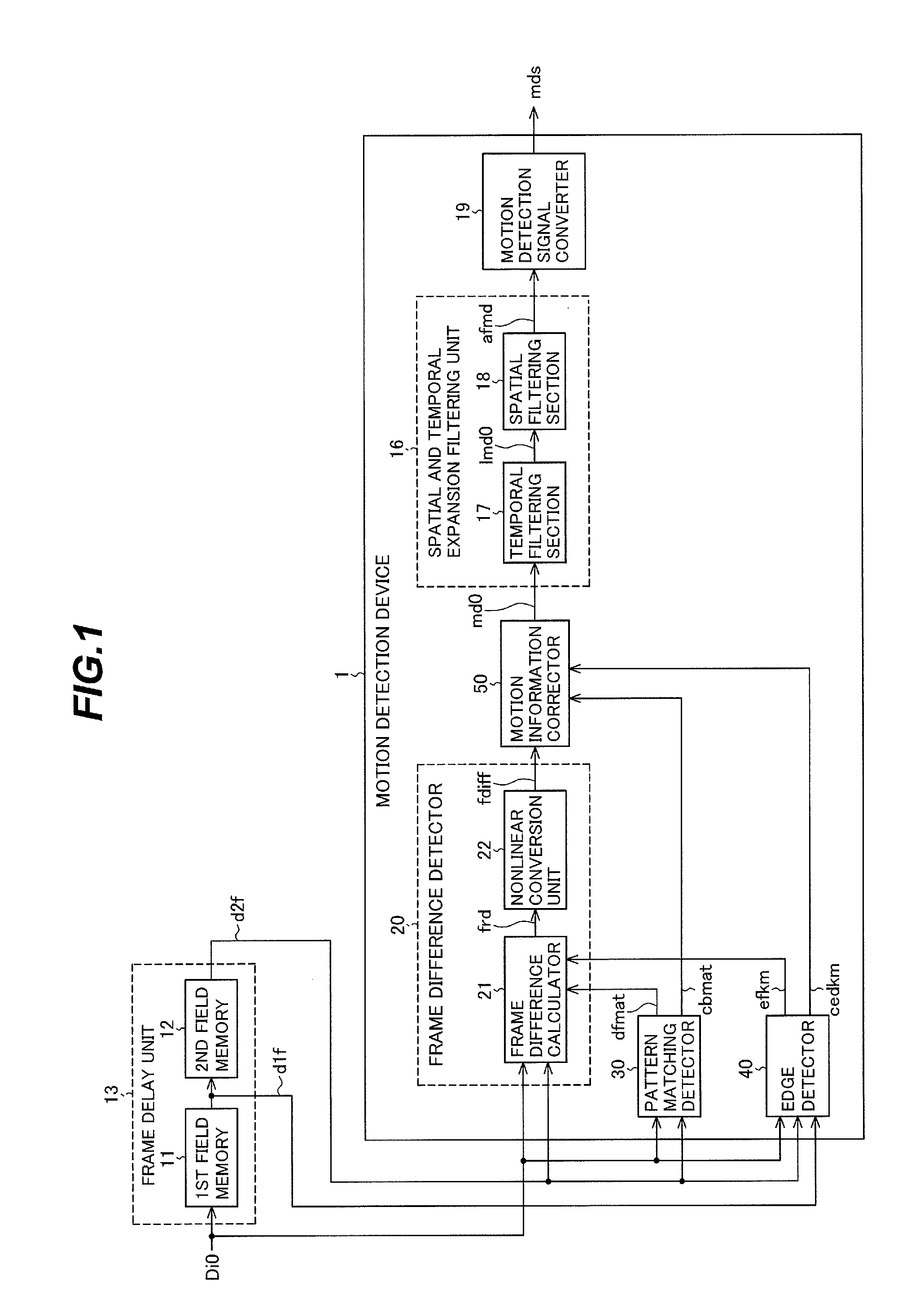
[0062]FIG. 1 is a block diagram showing the configuration of a video signal processing device of a first embodiment of the invention (device for implementing the video signal processing method of the first embodiment of the invention). The device is configured to detect image motion pixel by pixel from the video signals of a first frame and a temporally differing second frame: for example, from the video signal of the current frame and the video signal the preceding frame.

[0063]The video signal processing device of the first embodiment in FIG. 1 sequentially receives an interlaced input video signal Di0 indicating the values of the individual pixels constituting an input video picture. As shown in FIG. 1, the video signal processing device includes a frame delay unit 13 and a motion detection device 1.

[0064]The frame delay unit 13 includes first and second field memories 11, 12 that output a signal d1f delayed by one field (a one-field delayed signal) and a signal d2f delayed by one...

second embodiment

[0335]Whereas the video signal processing device in the first embodiment was configured to detect pixel motion in the image from the current frame signal and the signal one frame before and obtained frame differences between the current frame signal and the signal one frame before in its frame difference detector 20, the video signal processing device shown inFIG. 19 is configured to detect pixel motion in the image by obtaining a frame difference signal from frame differences between the current frame signal and the signal two frames before (two-frame differences) as well as from frame differences between the current frame signal and the signal one frame before.

[0336]FIG. 19 is a block diagram showing the configuration of a video signal processing device of the second embodiment of the invention (device for implementing the video signal processing method of the second embodiment of the invention). The device is configured to detect image motion pixel by pixel from the current frame...

third embodiment

[0386]The video signal processing devices in the first and second embodiments detected motion from a video signal locally, and can be applied in motion adaptive processing by processing the video signal according to the detected motion.

[0387]As an example of this type of application, a motion adaptive scan line interpolation process that performs scan conversion to convert an interlaced signal to a progressive signal (IP conversion) will be described.

[0388]In the third embodiment described below, during IP conversion, a video signal processing device generates an interpolated signal by switching between inter-field interpolation and intra-field interpolation according to the motion detection signal that indicates the amount or degree of motion detected. The motion detection device 1 in the video signal processing device in the first embodiment is used to detect motion.

[0389]FIG. 21 is a block diagram showing the configuration of a video signal processing device of the third embodime...


PUM


Abstract

In a motion detection device that detects motion from two frames of a video signal, a pattern matching detector determines pattern similarity between pixel blocks centered on a pixel of interest in the two frames to detect pattern motion. An edge detector detects edge presence and direction in a vicinity of the pixel of interest. A frame difference detector generates a smoothed frame difference signal for the pixel of interest. The smoothing is carried out within appropriate extents selected according to the detected pattern motion and edge direction. A motion information corrector generates motion information for the pixel of interest from the frame difference signal. Appropriate selection of the smoothing extent reduces motion detection mistakes. The motion information is useful in motion adaptive video signal processing.

Description

BACKGROUND OF THE INVENTION[0001]1. Field of the Invention[0002]The present invention relates to a motion detection device and method for use in motion adaptive signal processing of a video signal. The invention also relates to video signal processing devices and processing methods using the above motion detection device and method, and to a video display device using the processed video signal.[0003]2. Description of the Related Art[0004]Video signals are processed to enhance their displayed picture quality. The enhancement can be increased by detecting local image motion in the input video signal and carrying out motion adaptive signal processing. This is done by switching adaptively between processing suitable for still pictures and processing suitable for moving pictures, depending on whether the picture is locally still or moving. The two main types of motion adaptive signal processing carried out on television video signals are motion adaptive line interpolation and a type of ...

Claims


Application Information

Patent Timeline
Patent Type & Authority Applications(United States)
IPC IPC(8): H04N7/32H04N7/26H04N7/01
CPCH04N19/139H04N19/86H04N19/117
Inventor ASAMURA, MASAKOONO, YOSHIKI
Owner MITSUBISHI ELECTRIC CORP
Learn More