Parallel Hybrid-Electric Propulsion Systems for Unmanned Aircraft

a hybrid electric and unmanned aircraft technology, applied in process and machine control, instruments, navigation instruments, etc., can solve the problems of insufficient endurance and/or stealth attributes of current fielded aircraft, unable to provide the results sought by the military, and continued primitive guidance technology affecting the effectiveness of unmanned aviation

Inactive Publication Date: 2012-08-16
GOVERNMENT OF THE UNITED STATES AS REPRESENTD BY THE SEC OF THE AIR FORCE
View PDF3 Cites 222 Cited by
  • Summary
  • Abstract
  • Description
  • Claims
  • Application Information

AI Technical Summary

Benefits of technology

[0013]Embodiments of the invention address the need in the art by providing an unmanned air vehicle having an airframe and a parallel hybrid-electric propulsion system mounted on the airframe. In some embodiments, the parallel hybrid-electric propulsion system includes an internal combustion engine and an electric motor, with a hybrid controller configured to control both the internal combustion engine and the electric motor. A propeller connected to a mechanical link, which couples the internal combustion engine and the electric motor to the propeller, allows the internal combustion engine, the electric motor, or both to drive the propeller.

Problems solved by technology

However, the primitive guidance technology continued to hamper unmanned aviation's effectiveness for several more decades.
In the latter stages of World War II, radar guidance systems provided primitive attack drones a more capable means of navigation, but still did not provide the results sought by the military.
Despite the exponential increase in UAS employment, currently fielded aircraft lack the endurance and / or the stealth attributes desired by warfighters, among others.
Internal combustion engine driven aircraft possess adequate endurance for most ISR missions, but may acoustically alert those being monitored since their internal combustion engine driven counterparts generate mission compromising acoustic and thermal signatures.
Electric propulsion systems can be nearly silent and lack the strong thermal signatures associated with combustion.
However, electric systems suffer from dismal endurance times due to relatively low specific energies of current battery technology.
Each system possesses desired mission attributes, but neither is completely sufficient to meet the end goals of the military.
The practice of aircraft design can be a delicate balance between mission requirements.
Building a small stealthy aircraft capable of long endurance is counter to natural aerodynamic tendencies.
However, as the Reynolds number declines and the size of airfoils and power plants decrease, aerodynamic and thermodynamic efficiencies also drop.
Combining this fact with the intricacies of stealth design leads to a highly complex optimization problem.
Electric propulsion has many advantages, but brings an immense weight and endurance penalty to an aircraft due to the relatively poor specific energy of batteries.
However, the platforms have notable acoustic and thermal signatures making them either detectable at low altitudes or requiring them to maintain an altitude not conducive to effective sensor performance.
Electric platforms possess low acoustic and thermal signatures, but suffer from limited range due to the poor energy density available from even leading battery technology.

Method used


Image

  • Parallel Hybrid-Electric Propulsion Systems for Unmanned Aircraft
  • Parallel Hybrid-Electric Propulsion Systems for Unmanned Aircraft
  • Parallel Hybrid-Electric Propulsion Systems for Unmanned Aircraft

Examples


third embodiment

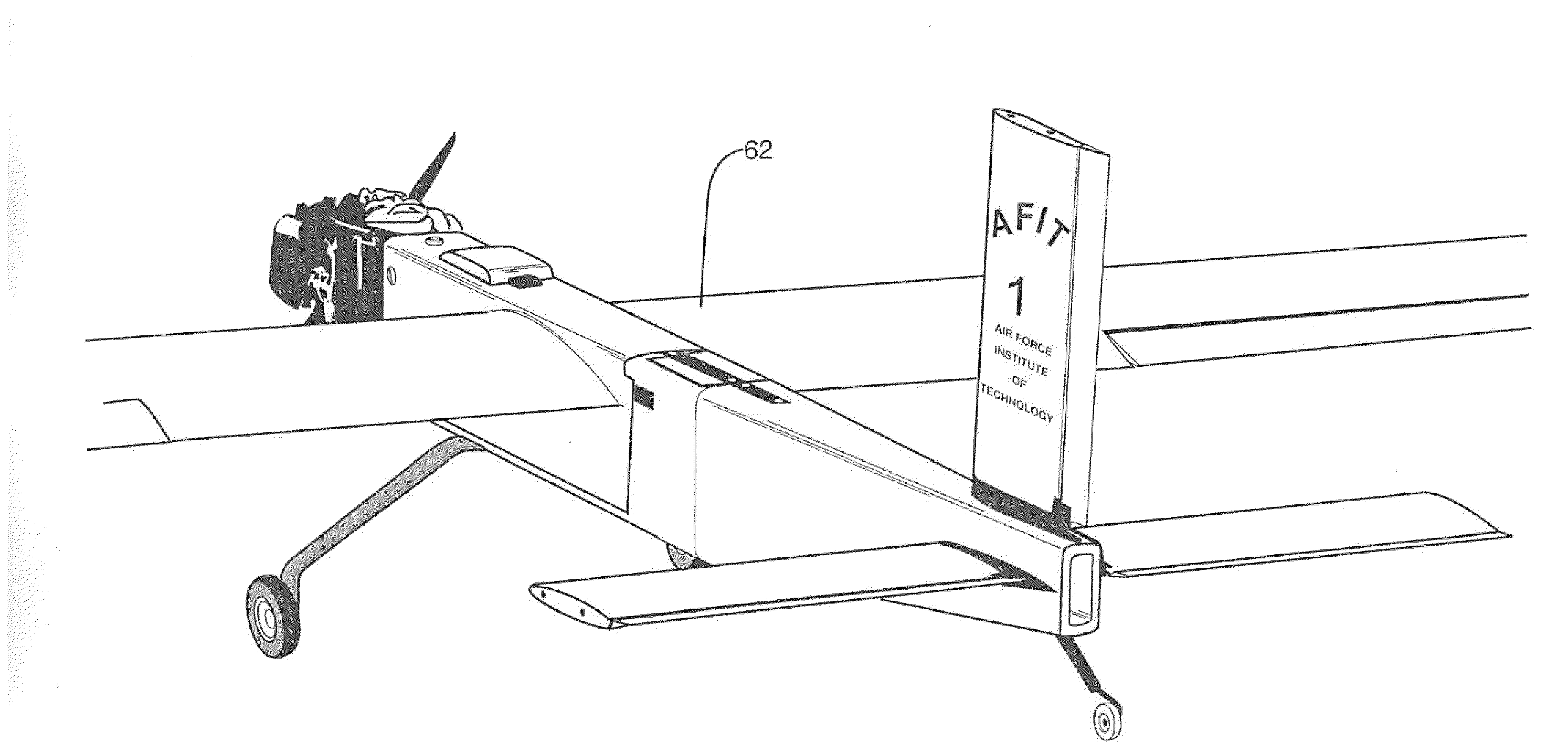
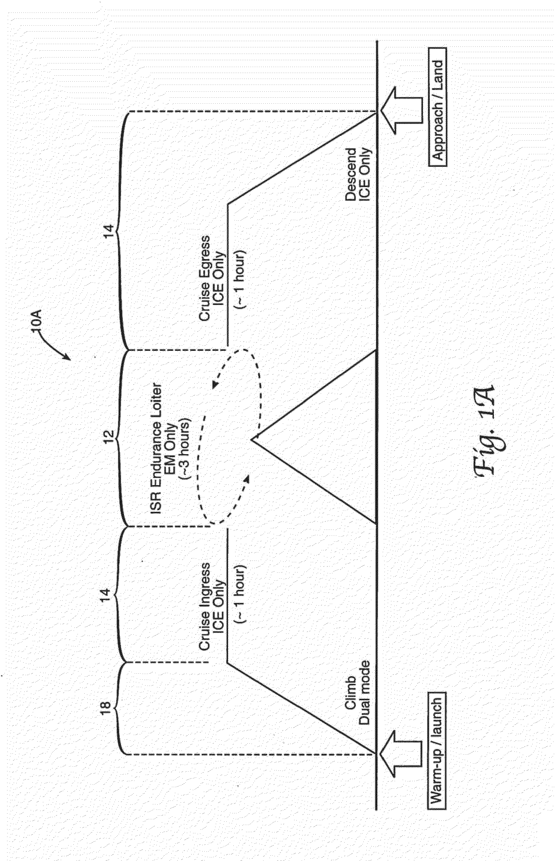
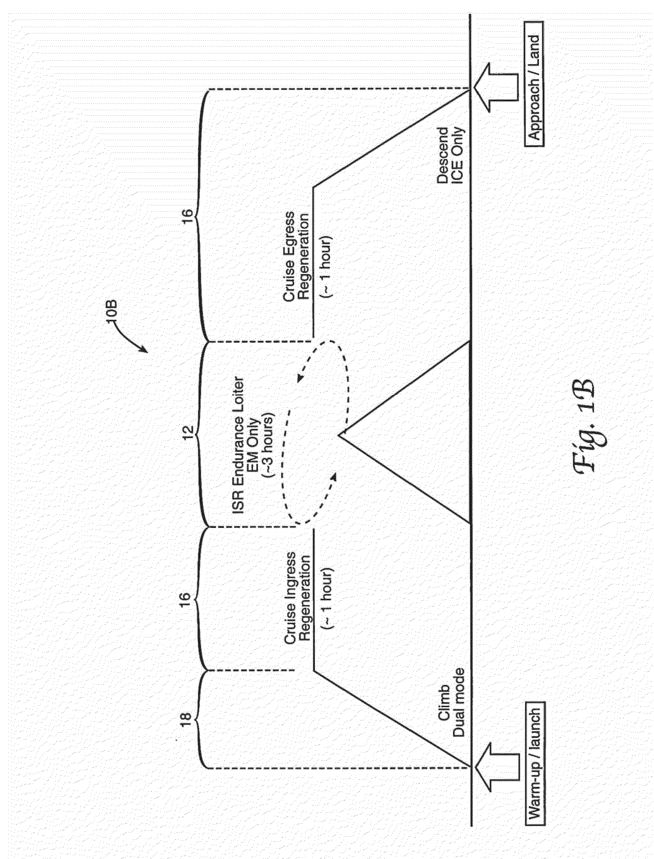
[0047]Two of the three embodiments, shown in FIGS. 2A and 2B, utilize an ICE 20 mechanically linked to an electric motor (EM) 22 to drive a propeller 24. The EM 22 may double as a generator during cruising operation to charge a battery pack in these embodiments. The third embodiment, shown in FIG. 2C, decouples the ICE 20 from the EM 22 and adds a second propeller 28 in a centerline-thrust configuration. In this embodiment, the battery pack 26 may be charged by wind-milling the second propeller 28 when cruising to turn the EM 22, though the recharging efficiency can be relatively low for this embodiment. For all three illustrated embodiments, the ICE 20 is powered by a conventional hydrocarbon fuel stored in a fuel tank 30. The ICE 20 in the embodiments shown in FIGS. 2B and 2C may be started or restarted with the use of a starter 32, whereas, the embodiment in FIG. 2A may utilize the EM 22 through a clutch 34 to start or restart the ICE 20. The clutch 34 may also be used to disenga...

second embodiment

[0052]The second embodiment, in FIG. 2B, provides a mechanically simpler option by adding a small electric starter 32 for the ICE 20, though other embodiments may utilize a mechanical starter in place of the electric starter 32. Rather than relying on the clutch 34 and matching the EM 22 and ICE 20 torques for starting purposes, a small, lightweight starter 32 may be attached to the ICE 20 and powered by the main battery pack 26. Like the previous embodiment, the electric-start configuration links the ICE 20 and the EM 22 to a single propeller 24 driveshaft 38. In addition, a controller (FIG. 3) may be coupled to at least one of the EM 22, ICE 20, starter 32, or battery pack 26. The avionics, flight control system and sensors may then be powered by the EM 22 acting as a generator during cruise flight. Again, the battery pack 26 may be used only to provide excess propulsion power and endurance operation. By eliminating the clutch 34, this configuration may provide a reliable and effi...

case 1

[0068] When the requested torque is less than the IOL Torque of the ICE at the speed as read from the torque map, the ICE provides the power for the aircraft.

ICEIOLTorque(rpm)>RequestedTorqueICEThrottle=RequestedTorqueICEMaxTorque(rpm)*100%(7)EMThrottle=0%(8)


PUM


Abstract

An unmanned air vehicle is provided, which includes an airframe and a parallel hybrid-electric propulsion system mounted on the airframe. The parallel hybrid-electric propulsion system includes an internal combustion engine and an electric motor. A hybrid controller is configured to control both the internal combustion engine and the electric motor. A propeller is connected to a mechanical link. The mechanical link couples the internal combustion engine and the electric motor to the propeller to drive the propeller. An alternate unmanned air vehicle includes a second propeller driven by the electric motor. In this alternate unmanned air vehicle, the internal combustion engine is decoupled from the electric motor.

Description

CROSS-REFERENCE TO RELATED APPLICATIONS[0001]This application claims the benefit of and priority to U.S. Provisional Application Ser. No. 61 / 442,914, entitled “Hybrid-Electric Propulsion System, Method, and Apparatus for Small Unmanned Aircraft Systems,” filed on Feb. 15, 2011, the entirety of which is incorporated by reference herein.RIGHTS OF THE GOVERNMENT[0002]The invention described herein may be manufactured and used by or for the Government of the United States for all governmental purposes without the payment of any royalty.BACKGROUND OF THE INVENTION[0003]1. Field of the Invention[0004]The present invention generally relates to air vehicles and, more particularly, to a dual engine hybrid electric air vehicle.[0005]2. Description of the Related Art[0006]Unmanned aviation emerged in the nineteenth century as aviation pioneers modeled their ideas for a practical means of manned flight. The first viable unmanned aircraft, including Charles Kettering's Liberty Eagle Aerial torpe...

Claims


Application Information

Patent Timeline
Patent Type & Authority Applications(United States)
IPC IPC(8): B64C19/02
CPCB64C39/024B64C2201/021B64C2201/042Y02T50/64B64D35/08B64D2027/026B64C2201/044Y02T50/60B64U50/11B64U10/25B64U50/19
Inventor HARMON, FREDERICK G.HISEROTE, RYAN M.RIPPL, MATTHEW D.AUSSERER, JOSEPH K.
Owner GOVERNMENT OF THE UNITED STATES AS REPRESENTD BY THE SEC OF THE AIR FORCE
Why Eureka
Try Eureka