Systems and Methods for Solar Energy Management

a technology of solar energy management and solar energy, applied in the direction of solar heat collector mounting/support, solar heat collector safety, light and heating apparatus, etc., can solve the problem that the material and installation cost of rigid posts and secure foundations can be prohibitive to the installation of a system of heliostats

Inactive Publication Date: 2012-08-23
GOOGLE LLC
View PDF3 Cites 0 Cited by
  • Summary
  • Abstract
  • Description
  • Claims
  • Application Information

AI Technical Summary

Benefits of technology

[0028]Various implementations of a solar energy system according to the present disclosure may include one or more of the following features and / or advantages. For example, the solar energy system may provide a relatively inexpensive structure for mounting solar energy members, such as heliostats, while maintaining sufficient rigidity for operation of the members. For instance, the system may maintain a heliostat mirror at an optimal position for reflecting sunlight towards a solar receiver even when subject to a wind load producing a bending moment on a supporting structure of the member. The system may also use relatively inexpensive tension cables to secure a heliostat support structure to a fixed surface when the structure is subject to a wind load that produces a bending moment of the structure. For instance, inexpensive tension-cables may be used in place of expensive structural foundations and beams to resist bending of a heliostat support structure. The system may also utilize a symmetric geometry to minimize angular deflections of a heliostat mirror (or other solar energy member) due to wind loads, thereby allowing the use of inexpensive, compliant materials that can flex significantly without adverse effect on the operation of the system. Further, the system may utilize inexpensive footings placed with minimal ground preparation and on-site installation cost as compared to expensive structural foundations of a heliostat support structure.

Problems solved by technology

Substantial wind forces on a planar object, such as a heliostat, may apply forces and torques which tend to knock the beam off-target.
One source of aiming errors of heliostats is the mechanical bending of a supporting structure under wind loads.
Often, the material and installation cost of rigid posts and secure foundations can be prohibitive to installation of a system of heliostats.
Further, the system may utilize inexpensive footings placed with minimal ground preparation and on-site installation cost as compared to expensive structural foundations of a heliostat support structure.

Method used


Image

  • Systems and Methods for Solar Energy Management
  • Systems and Methods for Solar Energy Management
  • Systems and Methods for Solar Energy Management

Examples


Embodiment Construction

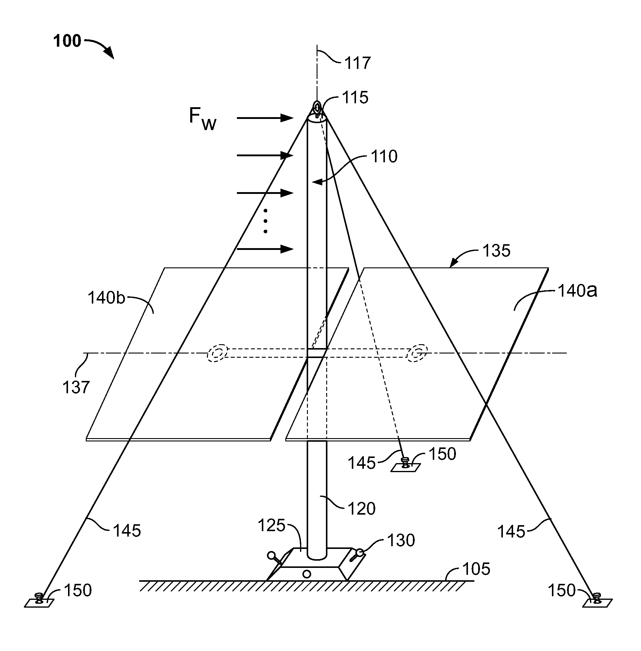
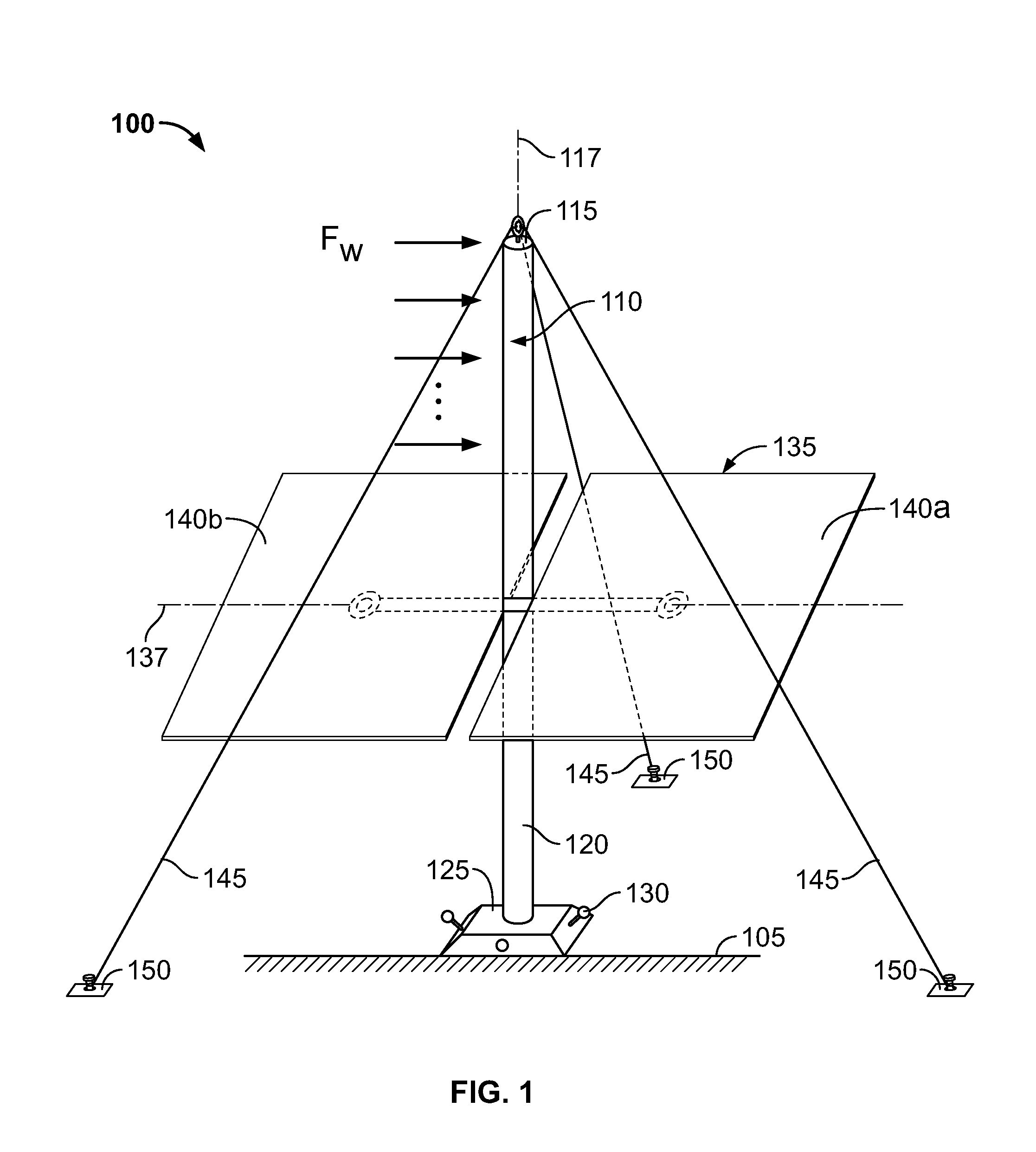
[0035]The present disclosure describes embodiments of a solar energy assembly and solar energy systems with an array (or multiple arrays) of solar energy assemblies. In one embodiment, a solar energy assembly according to the present disclosure may include a support structure with a substantially vertical structural member secured to a terranean surface by a footing structure. A solar energy member, such as a heliostat mirror or PV cell, may be mounted near a midpoint of the structural member for rotational and pivotal movement about orthogonal axes intersecting the midpoint of the structural member. Multiple cables are secured at first ends of the cables to a top portion of the structural member and at second ends of the cables to anchors. In some aspects, the support structure and cables may limit angular deflection of the solar energy member during lateral deflection of the structural member due to, for example, a wind load on the solar energy assembly.

[0036]FIG. 1 illustrates an...


PUM


Abstract

An apparatus includes a support member having a proximal end securable to a substantially fixed surface and a distal end opposite the proximal end; a solar energy member mounted to the support member at a location between the proximal and distal ends of the support member, where the solar energy member includes a first portion and a second portion arranged such that the support member extends substantially vertically between the two portions and the two portions are rotatable about a first axis to adjust azimuth of the solar energy member and about a second axis to adjust elevation of the solar energy member; and a plurality of cables, where each cable includes a first end secured to the distal end of the support member and a second end secured to a substantially fixed position, where the cables are configured to resist a wind load acting on the apparatus.

Description

CLAIM OF PRIORITY[0001]This application claims priority under 35 U.S.C. §119(e) to U.S. Provisional Patent Application Ser. No. 61 / 444,497 filed on Feb. 18, 2011, entitled “SYSTEMS AND METHODS FOR SOLAR ENERGY MANAGEMENT,” the entire contents of which are hereby incorporated by reference.TECHNICAL BACKGROUND[0002]This disclosure relates to systems and methods for solar energy management.BACKGROUND[0003]Solar energy management, collection, and use can often help alleviate energy problems around the world. In particular, solar energy systems such as photovoltaic (“PV”) systems, which generate electrical energy from solar energy can reduce dependence on fossil fuels or other power generation techniques. Additionally, solar energy may be used to generate heat that can subsequently be used in power generation systems. In some cases, solar energy collection systems may include multiple heliostats that reflect solar energy to a receiver. The receiver may then focus the reflected solar ener...

Claims


Application Information

Patent Timeline
Patent Type & Authority Applications(United States)
IPC IPC(8): F24J2/52F24J2/38F24S50/20
CPCF24J2/4638F24J2/5232Y02E10/47F24J2002/5286F24J2/5241F24S40/85F24S2025/017F24S25/50F24S25/12
Inventor GERSHONY, ZVIALLEN, TIMOTHY PETERGROON, JUNG SHIN
Owner GOOGLE LLC
Why Eureka
Try Eureka