Method and system for fuel vapor control

a technology of fuel vapor and emission control system, which is applied in the direction of electric control, water supply installation, machines/engines, etc., can solve the problems of inaccurate leak detection, insufficient purging of fuel vapor from the vehicle's emission control system, and inability to detect leakage, so as to reduce engine operation times, reduce fuel emissions benefits, and enable fuel economy

Active Publication Date: 2012-08-23
FORD GLOBAL TECH LLC
View PDF5 Cites 42 Cited by
  • Summary
  • Abstract
  • Description
  • Claims
  • Application Information

AI Technical Summary

Benefits of technology

[0002]Reduced engine operation times in hybrid vehicles, such as plug-in hybrid vehicles, enable fuel economy and reduced fuel emissions benefits. However, the shorter engine operation times can lead to insufficient purging of fuel vapors from the vehicle's emission control system. To address this issue, hybrid vehicles may include a fuel tank isolation valve (FTIV) between a fuel tank and a hydrocarbon canister of the emission system to limit the amount of fuel vapors absorbed in the canister. Specifically, the normally closed FTIV separates storage of refueling vapors from the storage of diurnal vapors, and is opened during refueling and purging to allow refueling vapors to be directed to the canister.

Problems solved by technology

However, the shorter engine operation times can lead to insufficient purging of fuel vapors from the vehicle's emission control system.
However, if the FTIV function is degraded, inaccurate leak detection may occur.
Further, to enable emissions compliance, in response to the indication of valve degradation, a leak detection operation may be disabled during a subsequent engine-on diurnal cycle.

Method used


Image

  • Method and system for fuel vapor control
  • Method and system for fuel vapor control
  • Method and system for fuel vapor control

Examples


Embodiment Construction

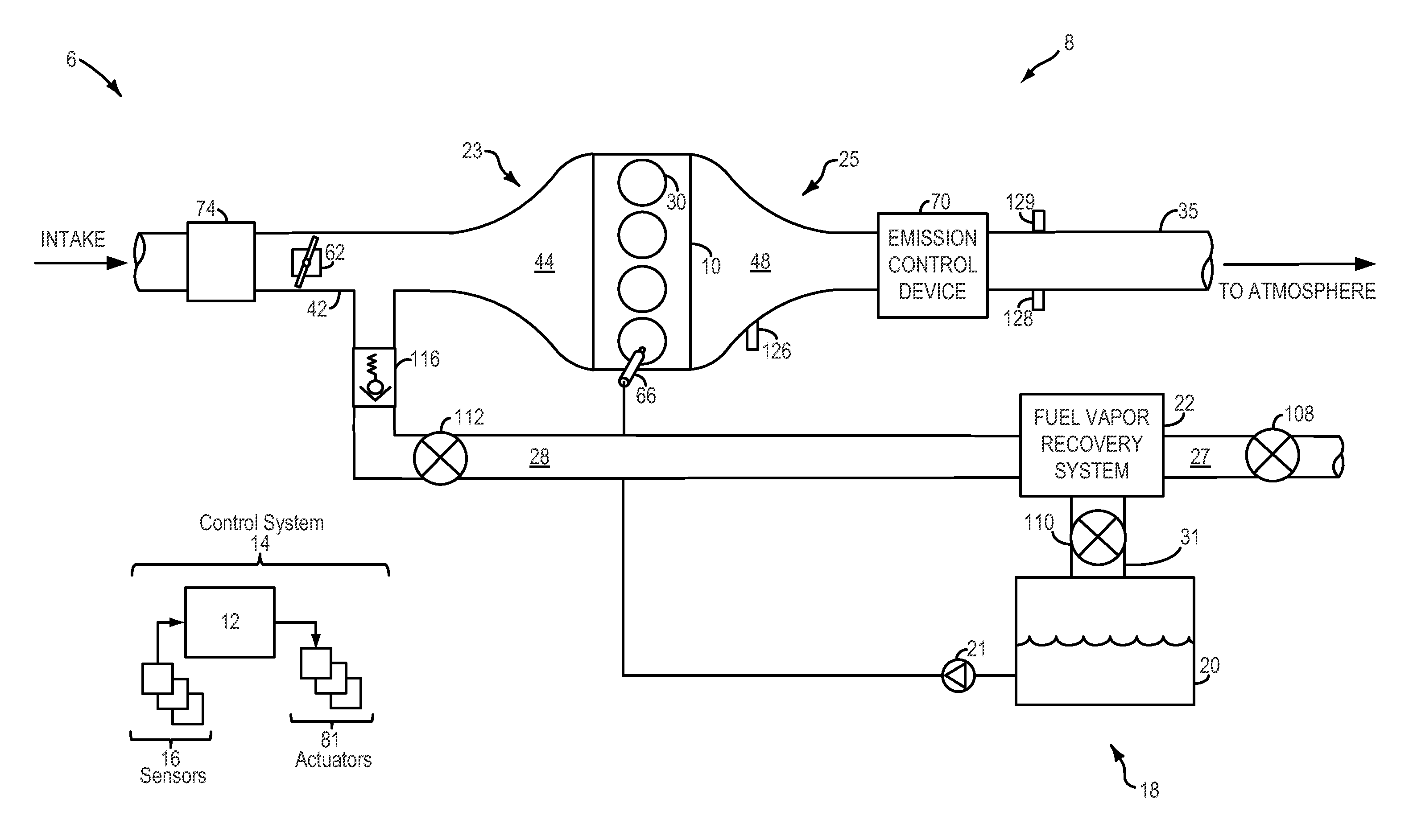
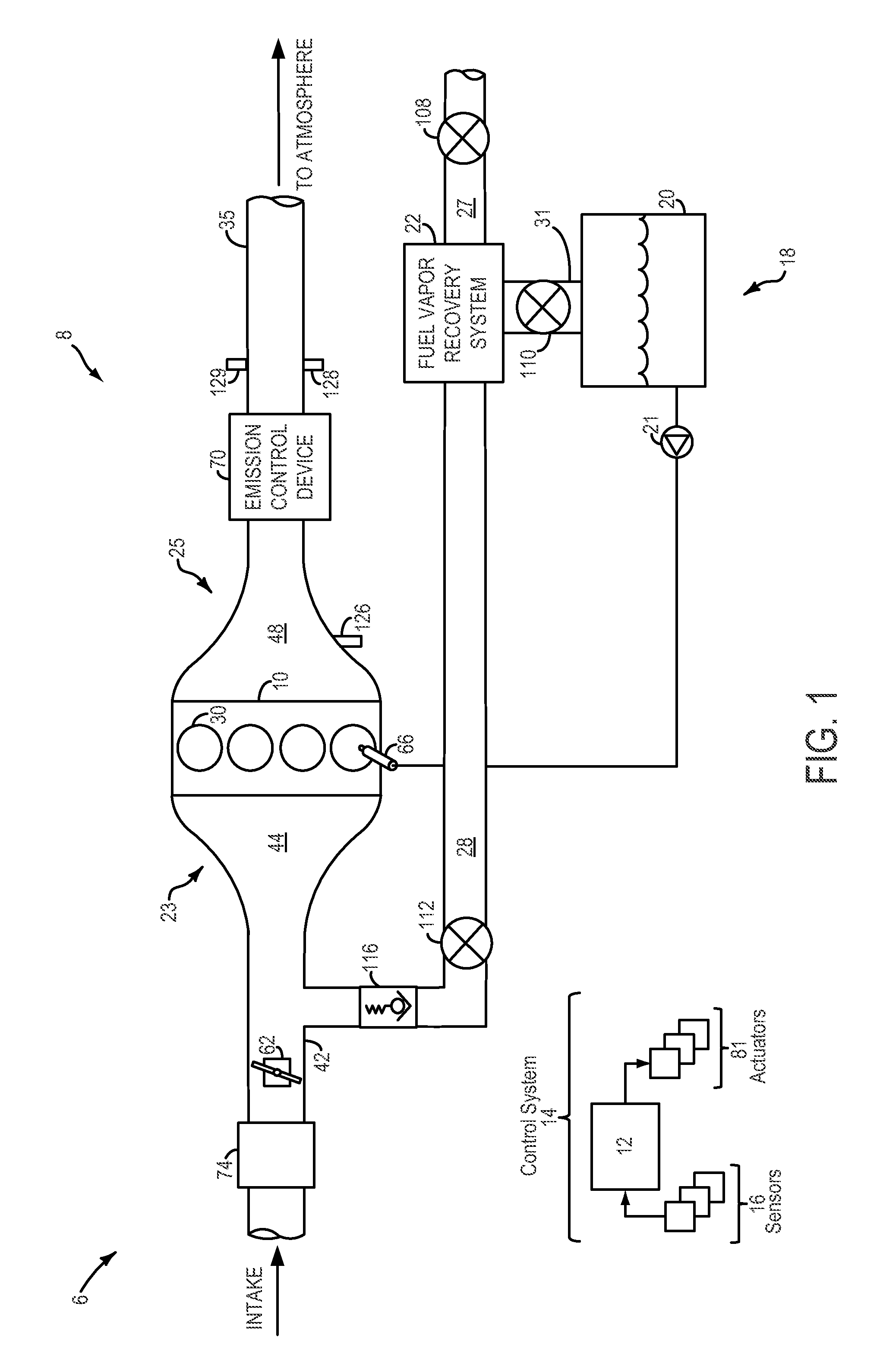
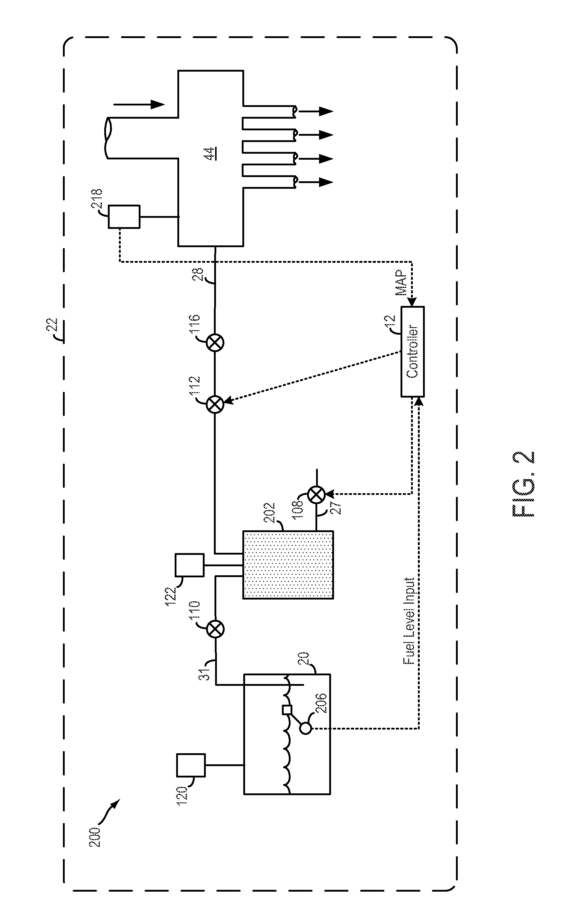
[0015]The following description relates to systems and methods for monitoring a fuel vapor recovery system, such as the system of FIG. 2, coupled to an engine system, such as the engine system of FIG. 1. During selected conditions, a fuel tank isolation valve (FTIV) of the fuel vapor recovery system may be modulated and pressure pulsations upstream and / or downstream of the valve may be monitored. Based on correlations between the valve modulation and the pressure pulsations, valve degradation may be indicated. Further, based on the functionality of the FTIV, fuel vapor recovery system operations (such as canister purging and leak detection) may be adjusted. An engine controller may be configured to perform diagnostic routines, such as those depicted in FIGS. 3-6, to identify valve degradation based on pressure pulsations responsive to the valve modulation, and to disable leak detection operations if the valve is degraded. Example maps that may be used to identify valve degradation a...


PUM


Abstract

Methods and systems are provided for monitoring a fuel vapor recovery system including a fuel tank isolation valve coupled between a fuel tank and a canister. During selected conditions, the valve is modulated and pressure pulsations in the fuel vapor recovery system are monitored. Valve degradation is identified based on correlations between the valve modulation and the resultant pressure pulsations.

Description

FIELD[0001]The present application relates to fuel vapor purging in vehicles, such as hybrid vehicles.BACKGROUND AND SUMMARY[0002]Reduced engine operation times in hybrid vehicles, such as plug-in hybrid vehicles, enable fuel economy and reduced fuel emissions benefits. However, the shorter engine operation times can lead to insufficient purging of fuel vapors from the vehicle's emission control system. To address this issue, hybrid vehicles may include a fuel tank isolation valve (FTIV) between a fuel tank and a hydrocarbon canister of the emission system to limit the amount of fuel vapors absorbed in the canister. Specifically, the normally closed FTIV separates storage of refueling vapors from the storage of diurnal vapors, and is opened during refueling and purging to allow refueling vapors to be directed to the canister.[0003]During leak detection operations, the FTIV is kept closed to better enable pressures and vacuums to be generated. Leaks are then detected based on pressur...

Claims


Application Information

Patent Timeline
Patent Type & Authority Applications(United States)
IPC IPC(8): F17D3/00F16K17/00
CPCF02D41/0032Y10T137/0379Y10T137/7722F02D41/003F02M25/0809G01M15/09
Inventor DUDAR, AED MOHAMMADJENTZ, ROBERT ROYDEBASTOS, TIMOTHYKERNS, JAMES MICHAELKLUZNER, MICHAEL IGOR
Owner FORD GLOBAL TECH LLC
Why Eureka
Try Eureka