LED package for uniform color emission

a technology of color emission and packaging, applied in the field of led packaging, can solve the problems of uneven phosphor distribution surrounding and relatively difficult dispersibility of silicon

Active Publication Date: 2012-08-23
HONG KONG APPLIED SCI & TECH RES INST
View PDF3 Cites 11 Cited by
  • Summary
  • Abstract
  • Description
  • Claims
  • Application Information

AI Technical Summary

Problems solved by technology

Various challenges exist in producing a LED with a high luminous output that is suitable for use as a light source in human environments.
Silicone, however, is relatively harder to dispense.
When the phosphor is dispersed within the encapsulating material, process control issues can result in uneven phosphor distribution surrounding the LED.

Method used


Image

  • LED package for uniform color emission
  • LED package for uniform color emission
  • LED package for uniform color emission

Examples


Embodiment Construction

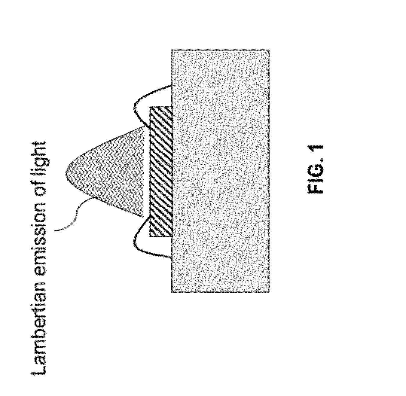
[0019]Turning to the drawings in detail, FIG. 4 depicts the angular intensity of LED light emission for an LED die. As can be seen in FIG. 4, the relative luminous intensity of emitted light drops by about 50% at an emission angle of plus or minus 60° and by about 90% at an emission angle of plus or minus 75°. Therefore it was discovered in the present invention that a uniform distribution of wavelength converting materials surrounding an LED die would generally result in insufficient wavelength converting material near the top of an LED covering layer (that is, the region having the greatest intensity of emitted light); similarly, a uniform distribution results in too large of a concentration of wavelength converting material positioned near the sides of an LED. As a result, the overall emitted light pattern would display undesirable non-uniform color characteristics. From this observation, the present invention was developed.

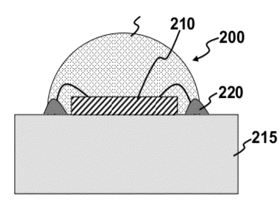
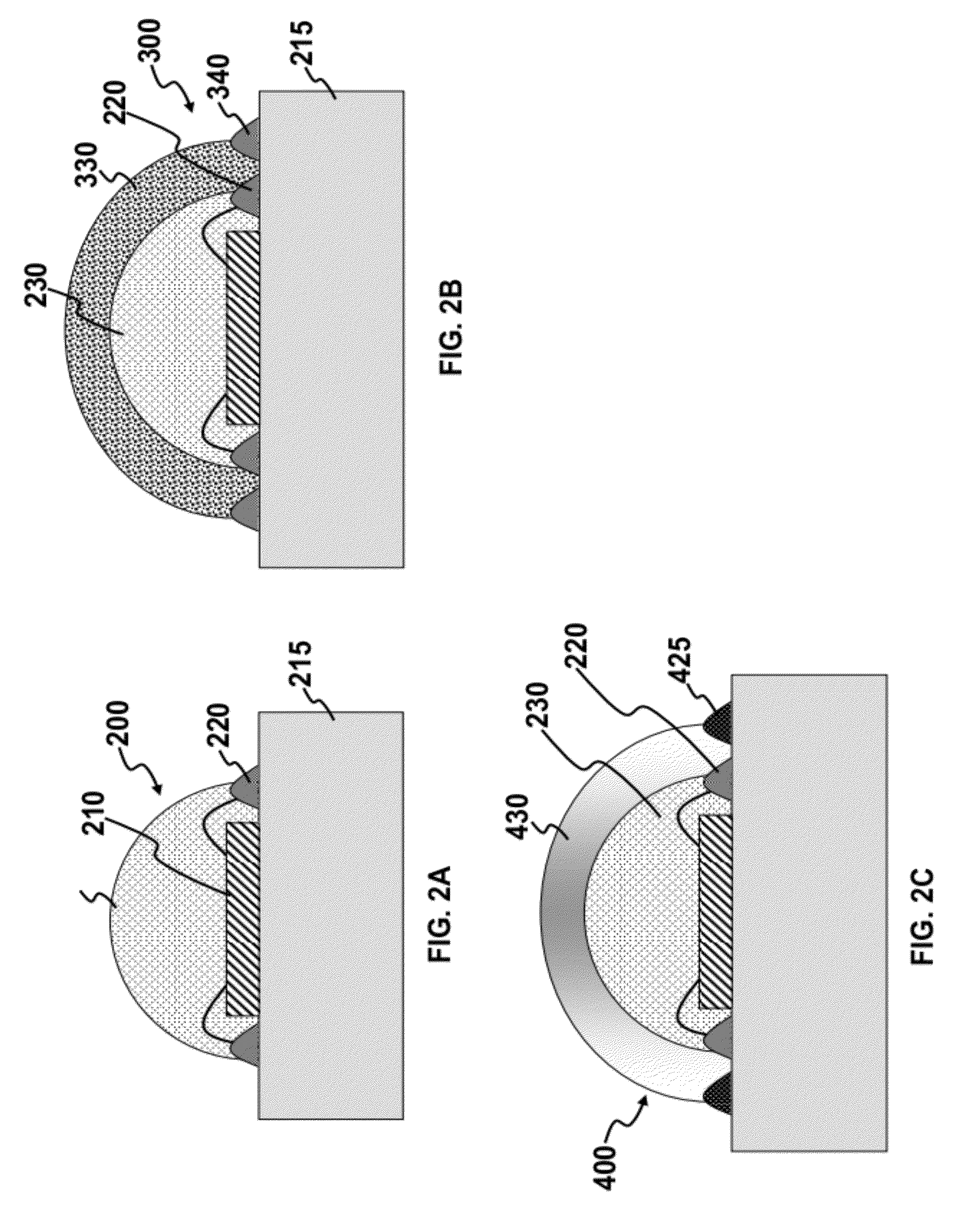
[0020]FIG. 2A schematically depicts a packaged light-emi...


PUM


Abstract

A light emitting diode package for one or more light emitting diodes mounted on a substrate. A frame is disposed on at least a portion of the substrate and substantially surrounds, but does not contact, the light emitting diode. The frame is substantially transparent to light emitted from the light emitting diode and includes one or more first wavelength converting materials. The wavelength converting materials, which may be one or more phosphors, convert at least a portion of light emitted at the emission wavelength to different wavelength. A cover covers the light emitting diode within the frame. The cover layer includes one or more second wavelength converting materials differing from the first one or more wavelength converting materials in wavelength converting material concentration or in converted light wavelength or in combinations of wavelength converting materials.

Description

TECHNICAL FIELD[0001]The present invention relates generally LED packaging. In particular it relates to a frame and a cover for light emitting diodes that provides improved color uniformity and luminous intensity, and methods of making the same.BACKGROUND[0002]A light emitting diode (“LED”) is a semiconductor light source. LEDs provide numerous advantages over other light sources such as incandescent lights. Amongst other advantages, LEDs typically have longer lifetimes, greater reliability, faster switching characteristics and lower energy consumption. Recent advances have produced LEDs with luminous intensities (lumen per Watt) that are comparable with or surpass incandescent lights.[0003]LED produce light by the spontaneous recombination of electron and hole pairs when the LED is forward biased above the threshold voltage in an electronic circuit. The wavelength of the light produced depends upon the band gap between the materials used in the p-n junction that form the LED. The w...

Claims


Application Information

Patent Timeline
Patent Type & Authority Applications(United States)
IPC IPC(8): H01L33/48H01L33/50
CPCH01L33/504H01L33/505H01L51/5253H01L51/524H01L51/5036H01L2224/48091H10K50/125H10K50/841H10K50/844H01L2924/00014
Inventor WAN, SHAN MEILEE, CHANG SHULU, MING
Owner HONG KONG APPLIED SCI & TECH RES INST
Why Eureka
Try Eureka