Device for an atomic clock

a technology of atomic clocks and devices, applied in the field of devices for atomic clocks, can solve problems such as unimplemented double-passage arrangements

Active Publication Date: 2012-08-23
ROLEX SA
View PDF13 Cites 27 Cited by
  • Summary
  • Abstract
  • Description
  • Claims
  • Application Information

AI Technical Summary

Problems solved by technology

Nevertheless, these double-passage arrangements have not been implemented for reasons of instability of the device and in particular because of disturbances of the laser provoked by the light back-reflected by the mirrors on to the laser.

Method used


Image

  • Device for an atomic clock
  • Device for an atomic clock
  • Device for an atomic clock

Examples


Embodiment Construction

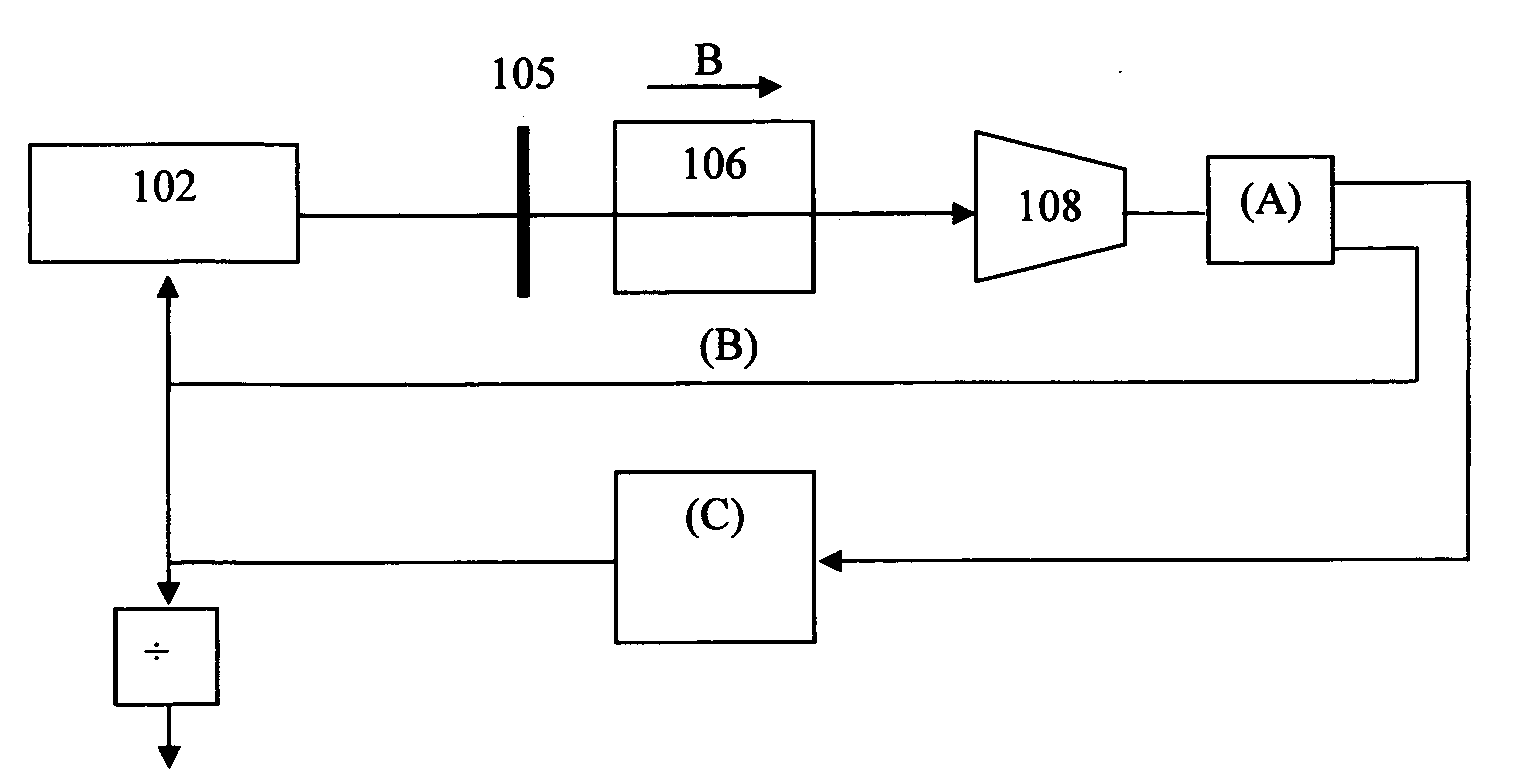
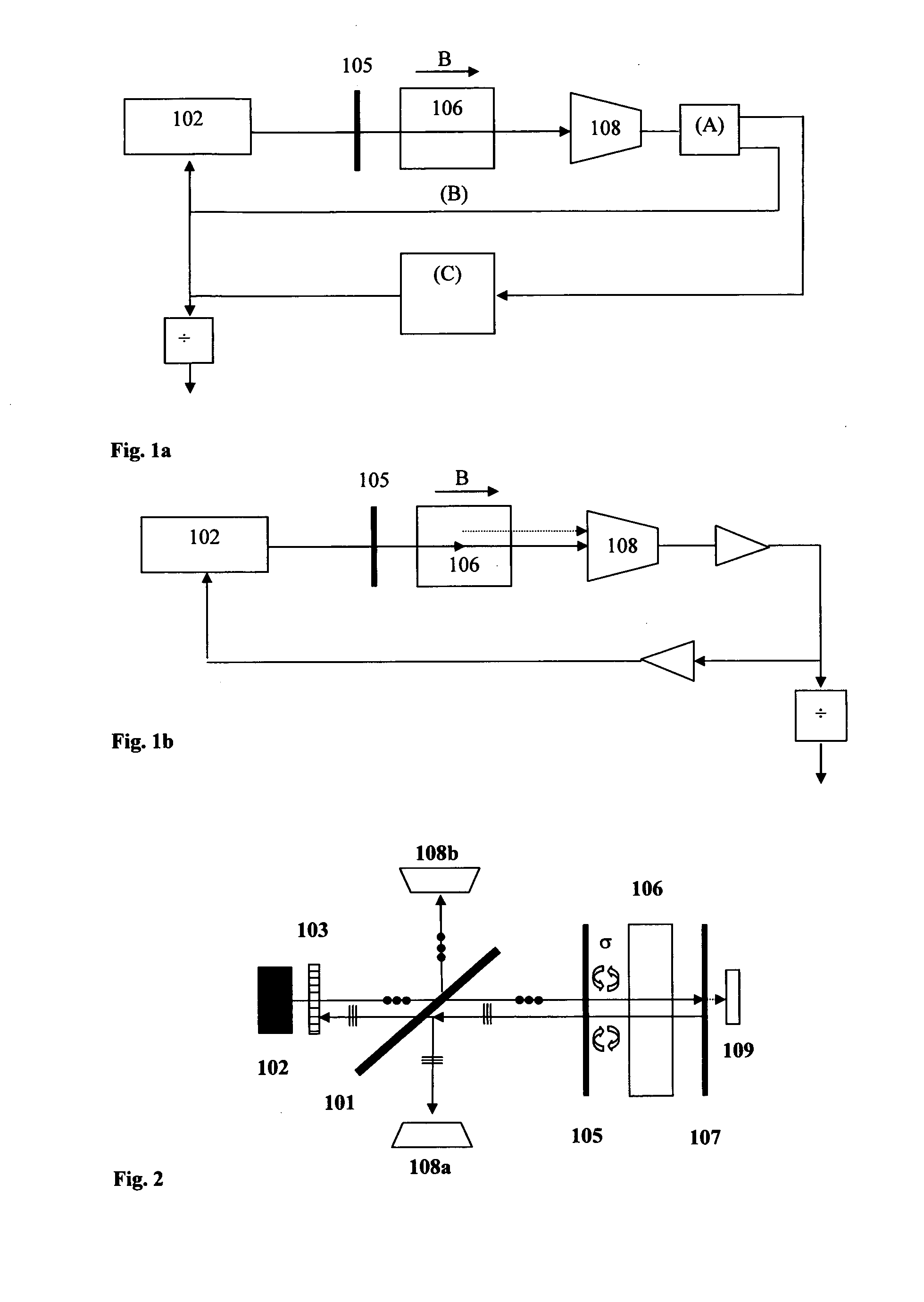
[0016]FIG. 1a illustrates the schematic diagram of the CPT atomic clock comprising a laser diode 102, a λ / 4 plate (or quarter-wave plate) 105, a gas cell (atomic) 106, a magnetic field B, a first photodetector 108, control electronics (A) and a microwave oscillator (C). The laser beam having passed through the gas cell 106 is picked up by the first photodetector 108 and is used by the control electronics to stabilize the frequency of the laser (B) and the frequency of the microwave oscillator (C).

[0017]FIG. 1b illustrates the schematic diagram of a closed loop mode Raman oscillator comprising a laser diode 102, a λ / 4 plate (or quarter-wave plate) 105, a gas cell (atomic) 106, a magnetic field B, a first photodetector 108, a microwave frequency divider, and an RF amplifier. The laser beam emitted by the laser diode 102 undergoes, in the gas cell 106, a light-atom interaction which generates a complementary beam called a Raman beam. The two light beams are picked up by the first photo...


PUM


Abstract

A device for an atomic clock, including: a laser source (102) that generates a laser beam; a splitter (101) that makes it possible to divert and allow a portion of the laser beam to pass therethrough in accordance with a predefined percentage; a quarter-wave plate (105) that modifies the linear polarization of the laser beam into circular polarization and vice versa; a gas cell arranged on the circular polarization laser beam; a mirror (107) sending the laser beam back toward the gas cell (106); a first photodetector (108a), and a polarizer (103) arranged between the laser beam outlet and the splitter in order to protect the laser source from the retroreflections emitted by different optical elements constituting the device.

Description

INTRODUCTION[0001]The present invention relates to the field of atomic clocks.STATE OF THE ART[0002]Miniature atomic clocks (with a volume of one cm3 or less), with low electrical consumption (less than one Watt) and which allow for portable applications are devices that have been made possible by the combination of the physical CPT (coherent population trapping) or Raman principles with an atomic clock architecture based on a gas absorption cell. These two physical principles do not require any microwave cavity to interrogate the reference atoms (typically rubidium or cesium) and thus eliminate the volume constraint associated with conventional cell-type atomic clocks. The physical part of the clock, which consists of the light source, the optical elements, the gas cell, the photodetector and all the functions such as heating and magnetic field generation, will be the subject of the considerations that follow. The implementation of technologies such as vertical cavity surface-emitt...

Claims


Application Information

Patent Timeline
Patent Type & Authority Applications(United States)
IPC IPC(8): H01S1/06
CPCG04F5/14G04F5/145H01S1/06H03L7/26H03B17/00
Inventor LECOMTE, STEVEHAESLER, JACQUES
Owner ROLEX SA
Why Eureka
Try Eureka