Optical parameter measuring apparatus and optical parameter measuring method

a technology of optical parameters and measuring methods, applied in the direction of optical radiation measurement, measurement devices, instruments, etc., can solve the problem of not being able to measure optical parameters in full, and achieve the effect of extending the range of measuring objects

Active Publication Date: 2012-08-23
NAT CHENG KUNG UNIV
View PDF10 Cites 7 Cited by
  • Summary
  • Abstract
  • Description
  • Claims
  • Application Information

AI Technical Summary

Benefits of technology

[0007]It is a non-limiting object of the exemplary embodiments to offer an optical parameter measuring apparatus and optical parameter measuring method which can handle extensive measuring to the optical parameter of one target. The exemplary embodiments may avoid complicated pretreatment and the purge process, and may further improve efficiency.
[0017]Accordingly, the exemplary embodiments may create an unprecedented derivate model for an optical parameter including establishing the Mueller matrixes of linear birefringence of the object, Mueller matrixes of circular birefringence of the object, Mueller matrixes of linear dichroism of the object, and Mueller matrixes of circular dichroism of the object. Further, Mueller matrixes of linear depolarization and circular depolarization of the object can be established to the object with scattering properties, and the Stokes vector is established according to these Mueller matrixes. Thus, nine optical parameters in the above optical properties can be solved in the form of decoupling. In other words, there are substantially no interferences among optical parameters and there is substantially no cross-talk effect.
[0018]Accordingly, the exemplary embodiments substantially integrate optical parameter measuring in a single measuring apparatus. Further, an optical parameter measuring apparatus and optical parameter measuring approach of this exemplary embodiment does not require parallel birefringence axis and dichroism axis of the object, and the range of measuring objects are extended.

Problems solved by technology

However, the related art optical parameter measuring apparatus measures only the optical parameter to some parts and some objects, but cannot extensively measure optical parameters, including, DSM 20 CD produced by OLIS.

Method used


Image

  • Optical parameter measuring apparatus and optical parameter measuring method
  • Optical parameter measuring apparatus and optical parameter measuring method
  • Optical parameter measuring apparatus and optical parameter measuring method

Examples


Embodiment Construction

[0027]The following examples refer to the disclosures to show an optical parameter measuring apparatus to this inventive concept. The same components will be illustrated with the same reference marks.

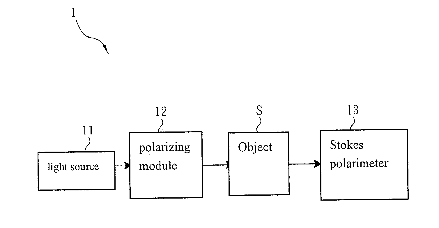
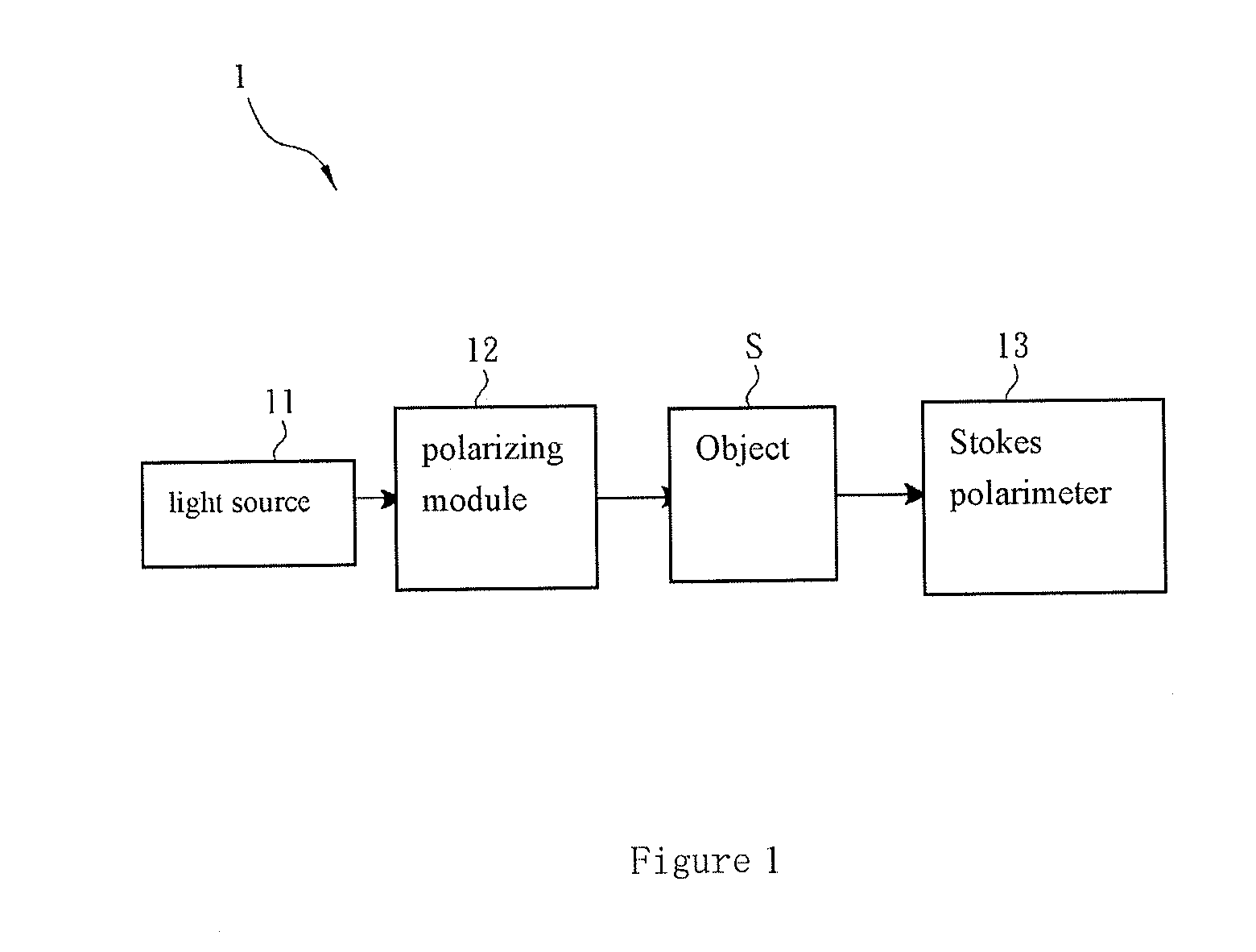
[0028]FIG. 1 is the sketch map of the optimized example of optical parameter measuring apparatus 1 according to an exemplary embodiment. Optical parameter measuring apparatus 1 is measures an optical parameter of object S, and consists of a light source 11, a polarizing module 12, a Stokes polarimeter 13 and a calculating module (not shown in this Figure).

[0029]This exemplary embodiment is directed to the category or applied range of the object S and it can include any target materials. For example, but not by way of limitation, such target material may include, tissue of a biological section, an optical components or the like. The object S could include anisotropic optical properties or scattering anisotropic optical properties. In the exemplary embodiment, object S is of anisotropic b...


PUM


Abstract

An optical parameter measuring apparatus for measuring optical parameters of an object includes a light source, a polarizing module, a Stokes polarimeter and a calculating module. The light source emits a light which is polarized by the polarizing module and received by the Stokes polarimeter. According to the light information generated by the Stokes polarimeter, Mueller matrixes of linear birefringence, circular birefringence, linear dichroism, circular dichroism and linear / circular depolarization of the object, and Stokes vector established according to the Mueller matrixes, the calculating module calculates the optical parameters.

Description

BACKGROUND[0001]1. Technical Field[0002]Aspects of the exemplary embodiments relate to an optical parameter measuring apparatus and optical parameter measuring approach, and more specifically, to an optical parameter measuring apparatus and optical parameter measuring approach taking use of Mueller matrixes and Stokes vector.[0003]2. Related Art[0004]Related art derivative products for the application of optical technology have extended to areas including displays, biological medicine and materials. Related art techniques exist with respect to optical parameter measuring approaches, including the measuring of linear birefringence of liquid crystal display (LCD's) compensator films, parameter measuring of circular birefringence for diabetics, parameter measuring of circular dichroism for protein structures, parameter measuring of linear dichroism for tumors, as well as the parameter measuring of scattering materials' surfaces of linear depolarization and circular depolarization.[0005...

Claims


Application Information

Patent Timeline
Patent Type & Authority Applications(United States)
IPC IPC(8): G01J4/00
CPCG01J4/04
Inventor LO, YU-LUNGPHAM, THI-THU-HIEN
Owner NAT CHENG KUNG UNIV
Why Eureka
Try Eureka