Network element clock synchronization systems and methods using optical transport network delay measurement

a technology of network element and optical transport network, applied in the field of network element clock synchronization system and method using optical transport network delay measurement, can solve the problems of unsuitable packet measurement accuracy, unsuitable for packet measurement, and added cost and complexity of network and network elements

Active Publication Date: 2012-08-23
CIENA
View PDF11 Cites 32 Cited by
  • Summary
  • Abstract
  • Description
  • Claims
  • Application Information

AI Technical Summary

Benefits of technology

[0003]In an exemplary embodiment, a method includes utilizing Optical Transport Network to perform a delay measurement between a first network element and a second network element; transmitting a time-stamped packet from the first network element to the second network element; receiving the time-stamped packet at the second network element; recovering a time stamp from the time-stamped packet; and utilizing the time stamp and the delay measurement to adjust the second network element. The method may further include utilizing the time stamp and the delay measurement to adjust a clock of the second network element to synchronize with a clock of the first network element. The method may further include operating a packet service over Optical Transport Network between the first network element and the second network element. The method may further include interconnecting the first network element and the second network element with a plurality of intermediate network elements therebetween and operating a packet service over Optical Transport Network between the first network element and the second network element. Optionally, the method may further include performing the delay measurement through Path Monitoring (PM) bytes in Optical Tr

Problems solved by technology

The accuracy of this synchronization directly affects the accuracy of the measurements.
This results in added cost and complexity to the network and the network elements.
The Network Timing Protocol (NTP) is also available to

Method used


Image

  • Network element clock synchronization systems and methods using optical transport network delay measurement
  • Network element clock synchronization systems and methods using optical transport network delay measurement
  • Network element clock synchronization systems and methods using optical transport network delay measurement

Examples


Embodiment Construction

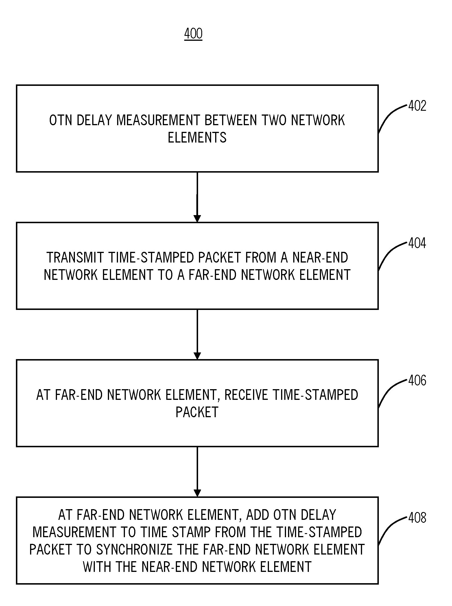
[0011]In various exemplary embodiments, the present invention relates to Network Element (NE) clock synchronization using Optical Transport Network (OTN) delay measurement systems and methods such as described in ITU-T G.709 (12 / 2009) “Interfaces for the Optical Transport Network (OTN)” and G.798 (10 / 2010) “Characteristics of optical transport network hierarchy equipment functional blocks”. OTN provides a Delay Measurement (DM) function to measure fiber path latency between two network elements to within microsecond accuracy. The convergence of packet switching and OTN transport into the same network element allows the sharing of this information between the two applications. The OTN delay measurement value can be used to synchronize two network element clocks to within microsecond accuracy without the need for a costly GPS synchronization solution or reduced accuracy NTP solutions.

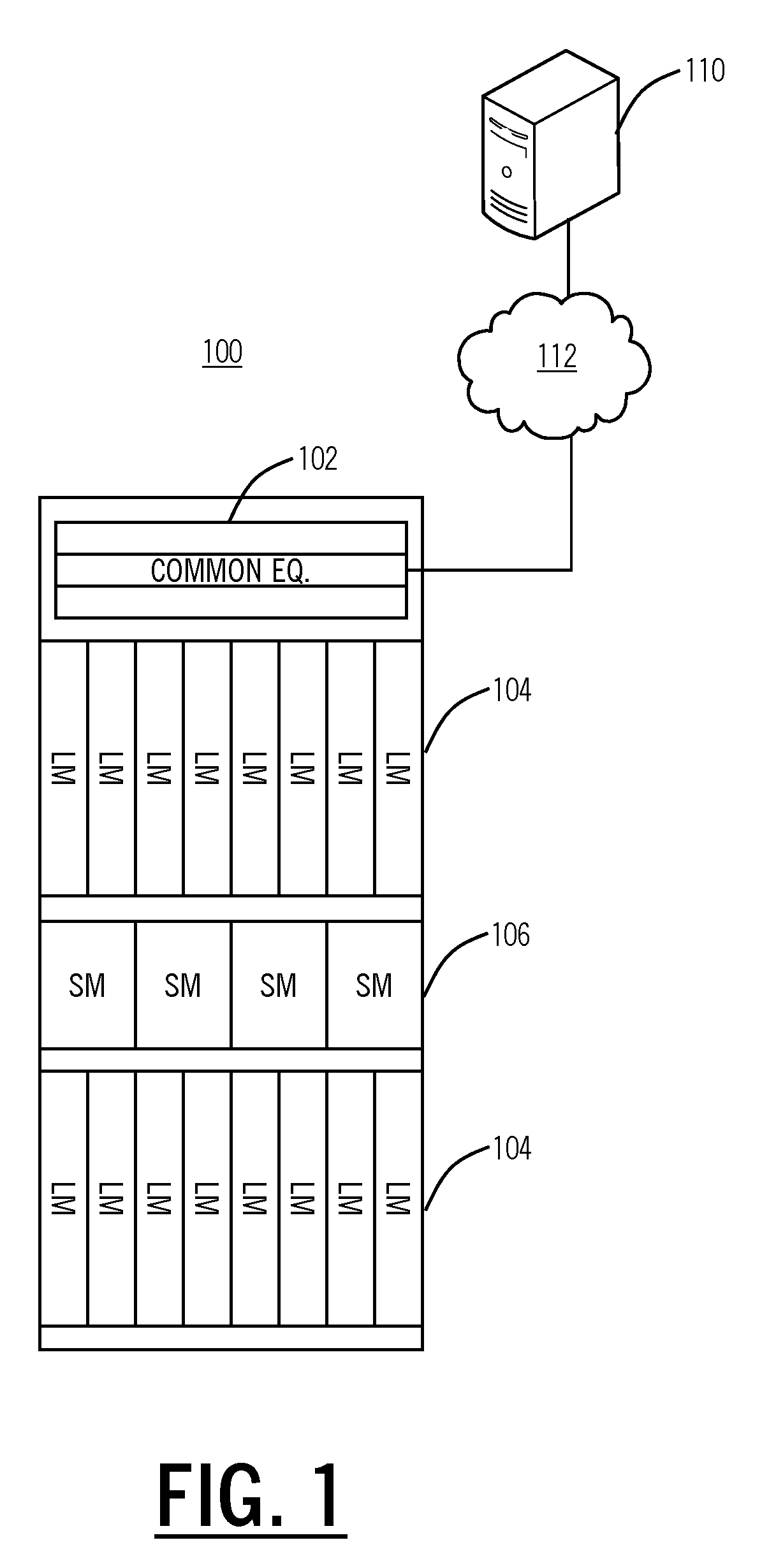
[0012]Referring to FIG. 1, in an exemplary embodiment, a block diagram illustrates an exemplary networ...


PUM


Abstract

The present disclosure provides Network Element (NE) clock synchronization using Optical Transport Network (OTN) delay measurement systems and methods such as described in ITU-T G.709 (12/2009) “Interfaces for the Optical Transport Network (OTN)” and G.798 (10/2010) “Characteristics of optical transport network hierarchy equipment functional blocks”. OTN provides a Delay Measurement (DM) function to measure fiber path latency between two network elements to within microsecond accuracy. The convergence of packet switching and OTN transport into the same network element allows the sharing of this information between the two applications. The OTN delay measurement value can be used to synchronize two network element clocks to within microsecond accuracy without the need for a costly GPS synchronization solution or reduced accuracy NTP solutions.

Description

FIELD OF THE INVENTION[0001]The present invention relates generally to networking systems and methods. More particularly, the present invention relates to Network Element (NE) clock synchronization systems and methods using Optical Transport Network (OTN) delay measurements such as described in ITU-T G.709 and G.798.BACKGROUND OF THE INVENTION[0002]Delay measurement in packet networks is a highly desirable feature for network operators. Synchronization of two network element clocks allows the system to perform one-way packet delay measurements, jitter measurements, and throughput measurements. The accuracy of this synchronization directly affects the accuracy of the measurements. These measurements need microsecond accuracy, requiring the network element clocks to also have microsecond synchronization accuracy. Currently, the only way to guarantee microsecond accuracy is to use Global Positioning Satellite (GPS) synchronization at both network elements. The GPS solution requires eac...

Claims


Application Information

Patent Timeline
IPC IPC(8): H04B10/00H04B10/08
CPCH04J3/1658H04J3/0682H04L7/0054H04L9/12H04L25/247H04L27/2653
Inventor MOYNIHAN, JEFFREY SCOTT
Owner CIENA
Why Eureka
Try Eureka