Exhaust line with injection system

a technology of exhaust gas and injection system, which is applied in the direction of machines/engines, engine components, mechanical apparatus, etc., can solve the problems of incompressible link, urea into ammonia, and the mixture between ammonia and exhaust gases requires time and significant path distan

Active Publication Date: 2012-08-30
FAURECIA SYST DECHAPPEMENT
View PDF5 Cites 97 Cited by
  • Summary
  • Abstract
  • Description
  • Claims
  • Application Information

AI Technical Summary

Benefits of technology

[0010]The injection section comprises at least a first cup arranged inside the circulation channel in the path of the exhaust gas flow such that an average path of exhaust gas jets is higher by at least 20% in relation to the predetermined length.

Problems solved by technology

Such an arrangement imposes an incompressible link, in particular due to the presence of the convergent and divergent cones.
This conversion of the urea into ammonia and the mixture between the ammonia and the exhaust gases require time, and therefore a significant path distance.
Nevertheless, such an arrangement with a reduced distance is delicate and costly to produce.

Method used


Image

  • Exhaust line with injection system
  • Exhaust line with injection system
  • Exhaust line with injection system

Examples


second embodiment

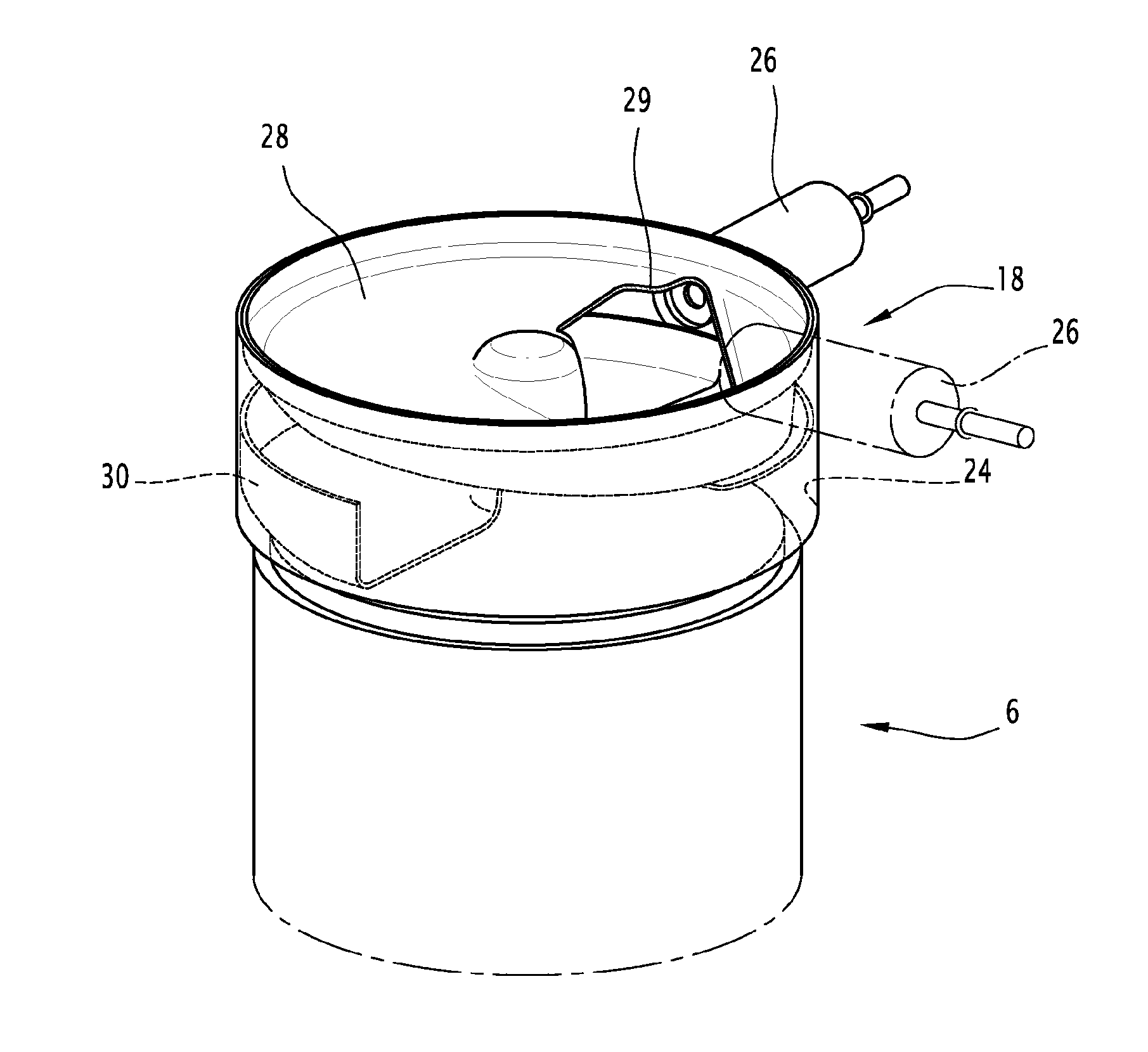
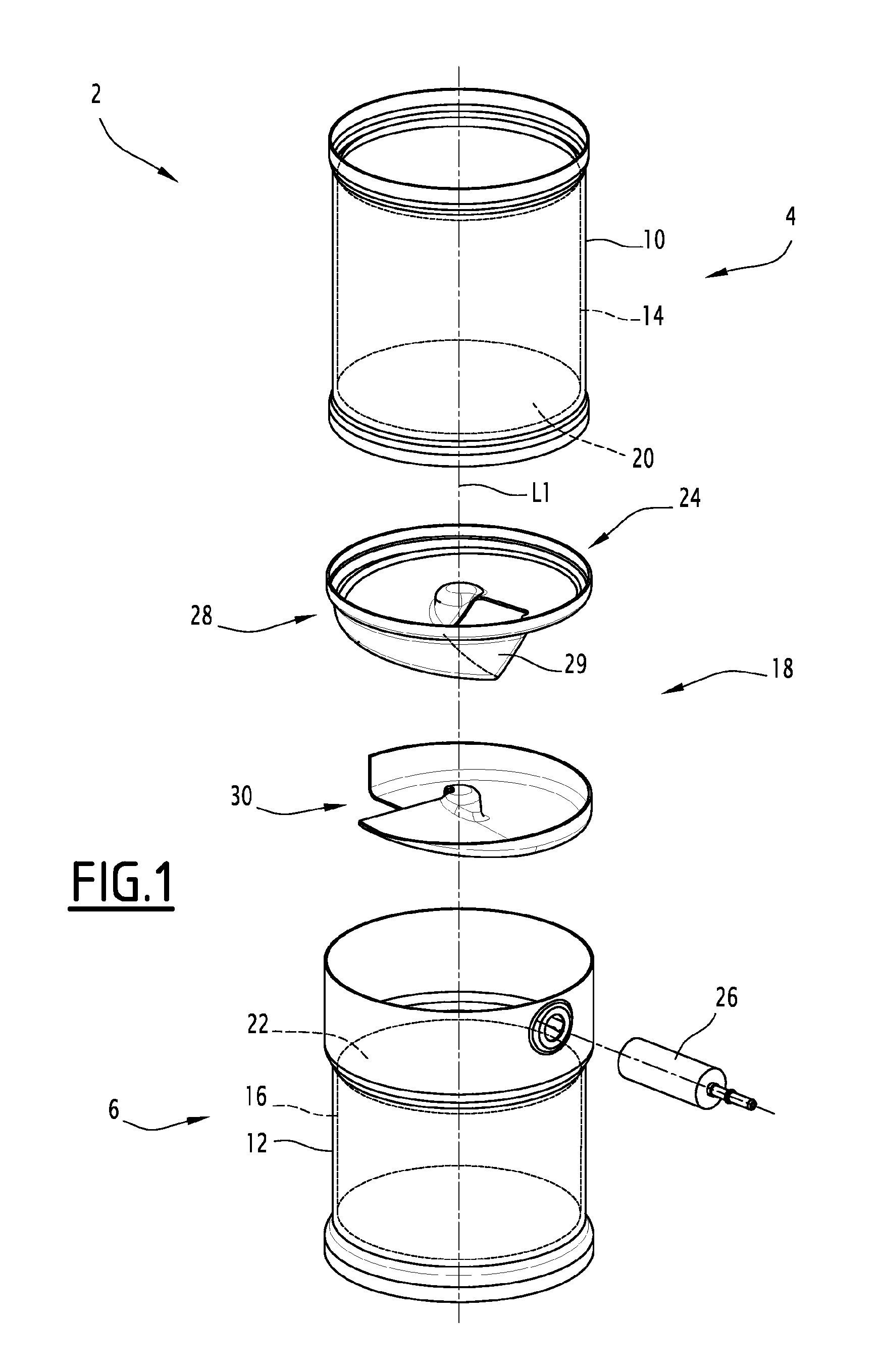
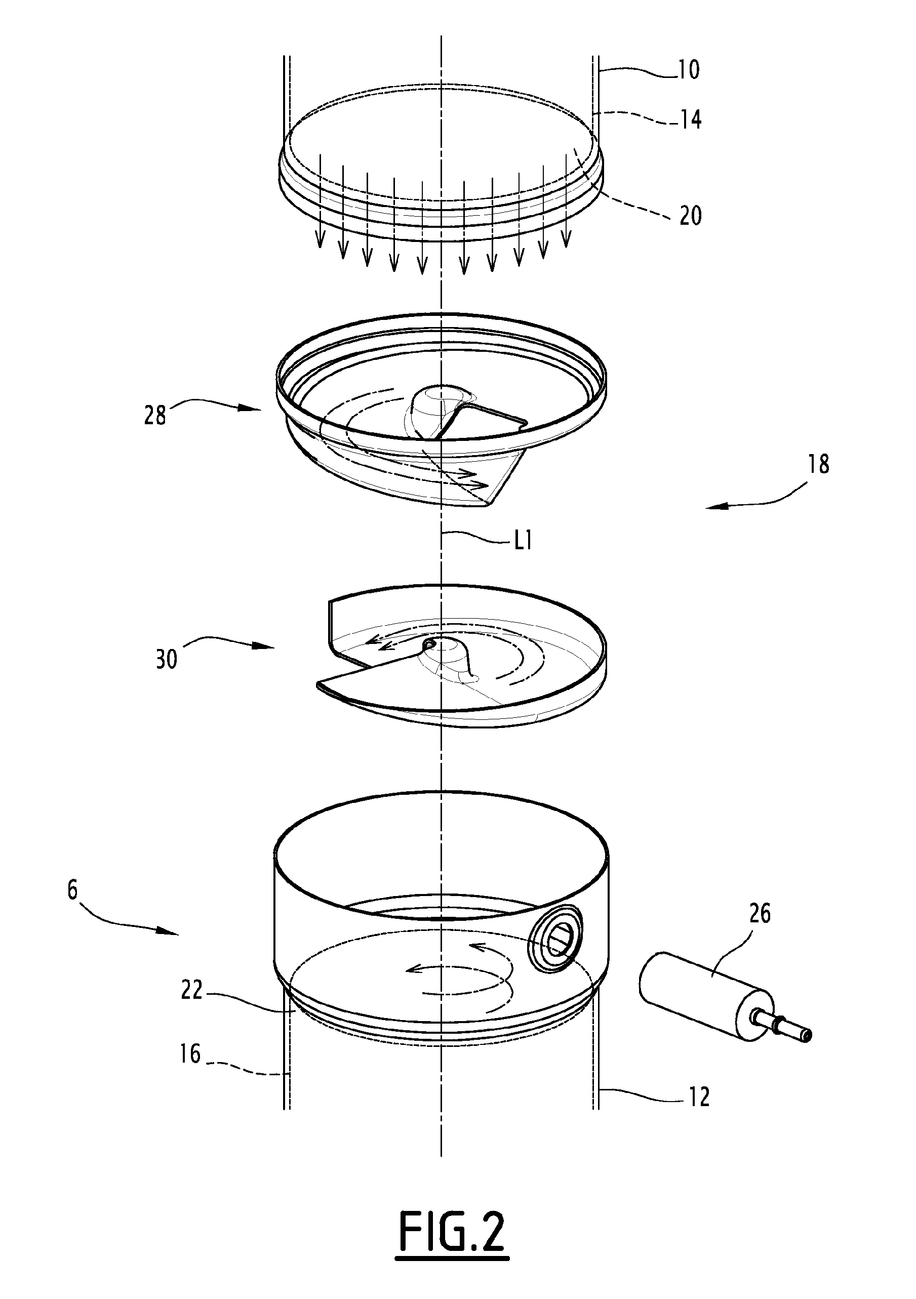
[0088]the injection section 318 is illustrated in FIGS. 8 (profile view), 9 and 10 (perspective views). The injection section 318 comprises a first cup 328 and a second cup 330.

[0089]The outer enclosure 12 of the downstream exhaust gas processing device 6 is sealably fixed to the exhaust gases at the lower portion of the outer enclosure 10 of the upstream exhaust gas processing device 4. The downstream block 16 and the two cups 328, 330 are inside the downstream outer enclosure 12.

[0090]The first cup 328 has a bottom winding in a spiral around the central line L1 of the injection section 318. The first cup 328 has a concavity facing the downstream face 22, such that the bottom of the first cup 328 forms a lid of the second cup 330.

[0091]The first cup 328 has a large opening 329 at the end of the spiral closest to the upstream face 20. The opening 329 is inclined both relative to the central line L1 and relative to a plane perpendicular to the central line L1.

[0092]The first cup 328 ...

third embodiment

[0114]the injection section 418 is illustrated in FIGS. 11, 12 (profile views) and 13 (perspective view). The injection section 418 comprises a first cup 428 and a second cup 430.

[0115]The outer enclosure 12 of the downstream exhaust gas processing device 6 is fixed sealably to the exhaust gases at the outer enclosure 10 of the upstream exhaust gas processing device 4 via the second cup 430. The two cups 428, 430 are arranged at the junction between the upstream 10 and downstream 12 outer enclosures, the first cup 428 being inside the upstream outer enclosure 10 and the second cup 430 being inside the downstream outer enclosure 12.

[0116]The first cup 428 opens toward the downstream face 22 and comprises a rounded wall with no sharp edges. This wall has a hollow central zone 450 facing the upstream face 20 and a peripheral zone 452 protruding toward the upstream face 20 surrounding the hollow central zone 450. The protruding peripheral zone 452 comprises a lower peripheral section 45...


PUM


Abstract

An exhaust line has upstream and downstream blocks for processing exhaust gases. An injection section is arranged between an upstream face defined by the upstream block and a downstream face defined by the downstream block and includes a circulation channel for the exhaust gas flow extending from the upstream face to the downstream face. The channel includes a central line having a determined length between the upstream and downstream faces. The injection section includes a reagent injector capable of injecting a reagent into the injection section. The injection section has a first cup inside the circulation channel in the flow path such that the average path of exhaust gas jets is higher by at least 20% in relation to the predetermined length. A second cup is arranged inside the circulation channel between the upstream face and the first cup. The reagent is done between the first cup and the second cup.

Description

RELATED APPLICATION[0001]This application is the U.S. national phase of PCT / FR2010 / 051131, filed Jun. 8, 2010, claiming priority to FR 09 5199, filed Jun. 19, 2009.TECHNICAL FIELD[0002]The present invention generally relates to exhaust lines for automobiles equipped with reducing agent injection devices for a selective reduction catalyst of the exhaust gases of an engine.[0003]An automobile exhaust line, of the type comprises upstream and downstream blocks for processing exhaust gases flowing in an exhaust line. The upstream and downstream blocks are arranged in series in the exhaust line. An injection section is arranged between an upstream face defined by the upstream block and a downstream face defined by the downstream block. A circulation channel for the exhaust gas flow extends from the upstream face to the downstream face. The channel includes a central line having a determined length between the upstream and downstream faces. The injection section includes a reagent injector...

Claims


Application Information

Patent Timeline
Patent Type & Authority Applications(United States)
IPC IPC(8): F01N3/20
CPCF01N3/2066F01N3/2892F01N13/08F01N13/0097F01N2610/02F01N2610/14Y02T10/24F01N2240/20Y02A50/20Y02T10/12B01F23/213B01F25/423F01N3/20F01N3/24F01N3/28
Inventor GREBER, FREDERICPERROT, YOHANNBRUNEL, JEAN-PAUL
Owner FAURECIA SYST DECHAPPEMENT
Why Eureka
Try Eureka