
Wire roll stand with individual drive
a technology of individual drive and roll stand, which is applied in the field of roll stand, can solve the problems of inability to adapt the cross sectional acceptance per roll pass, the inability to control the tension or longitudinal pressure of the wire rod strand, and the overheating of the rolled product core or exceeding the shape change limit of the material, etc., and achieves high flexibility.
- Summary
- Abstract
- Description
- Claims
- Application Information
AI Technical Summary
Benefits of technology
Problems solved by technology
Method used
Image

Examples
Embodiment Construction
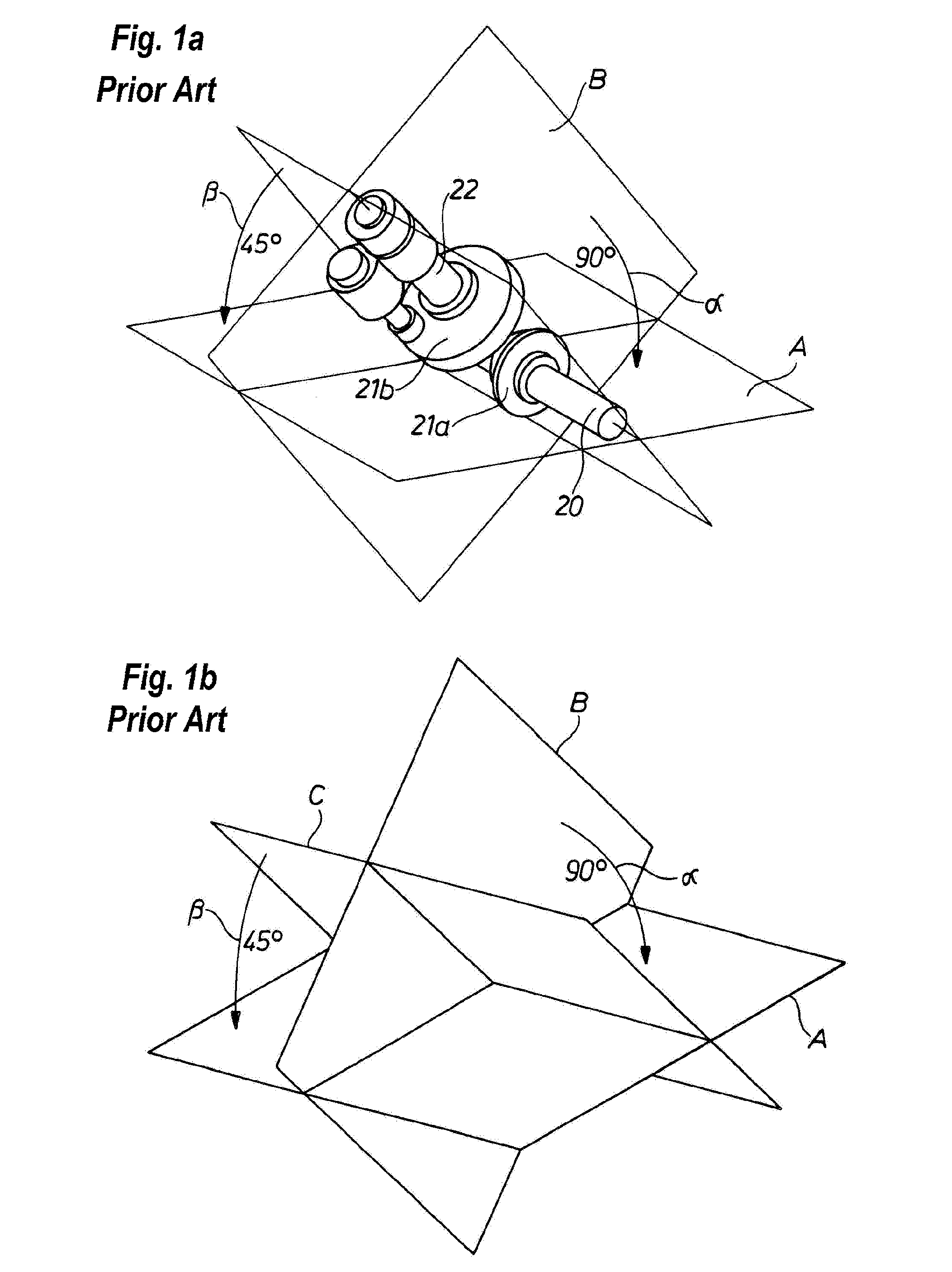
[0052]FIG. 1a shows a diagrammatic sectional view of a drive train of a wire roll stand (not shown) according to the prior art as well as an illustration of the bend angle α, β between the planes A, B, C inside the drive. Half of the roll stands of a roll block arranged in a V-shape at an angle of 45° to the mill floor are driven via a common drive shaft 20. The roll stand drive shaft 22 is driven via a bevel gear transmission 21, comprising two bevel gears 21a, 21b set at an angle of 90° to one another. This roll stand drive shaft 22 in turn extends (not shown) to a transmission (not shown) for driving the rolls or roll rings (not shown) of the roll stand. The entire drive of the roll stand according to the prior art thus has two spatial bends or deflections, namely a first bend by an angle α=90° between the plane A parallel to the mill floor and in which the drive shaft 20 extends, and plane B that is perpendicular to the plane A and in which the roll stand drive shaft 22 extends,...
PUM
| Property | Measurement | Unit |
|---|---|---|
| Angle | aaaaa | aaaaa |
| Angle | aaaaa | aaaaa |
| Angle | aaaaa | aaaaa |
Abstract
Description
Claims
Application Information