

High frequency rotary transformer for synchronous electrical machines
a technology of synchronous electrical machines and transformers, which is applied in the direction of motor/generator/converter stoppers, continuously variable inductance/transformers, dynamo-electric converter control, etc., can solve the problems of brushes, long-term durability, and unsatisfactory approach,
- Summary
- Abstract
- Description
- Claims
- Application Information
AI Technical Summary
Benefits of technology
Problems solved by technology
Method used
Image

Examples
Embodiment Construction
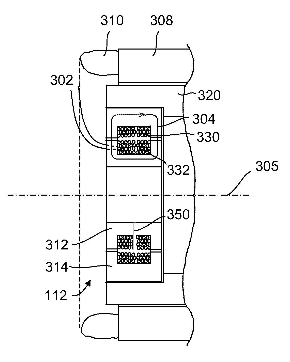
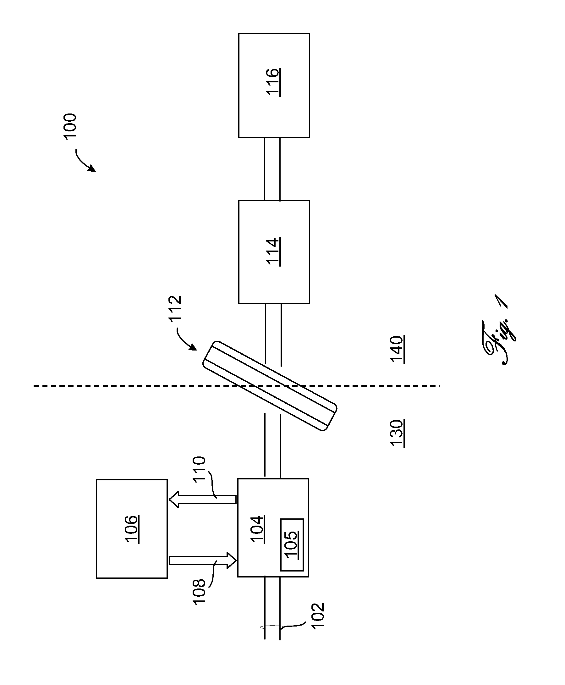
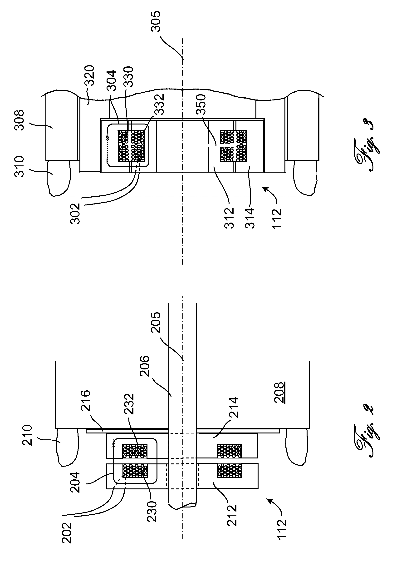
[0005]In accordance one embodiment of the invention, a high frequency rotary transformer for an electrical machine includes a primary transformer component having a primary transformer winding, and a secondary transformer component having a secondary transformer winding. The primary transformer winding is configured to be coupled to a DC power source via a DC-AC converter (inverter). The secondary transformer winding is configured to be coupled (e.g., indirectly, through a rectifier / filter circuit) to a winding of the rotor. Each of the primary and secondary transformer components are mechanically coupled to either the stator or the rotor. The secondary transformer component is configured to rotate with respect to the primary transformer component. The AC current in the primary produces a magnetic flux via the primary transformer winding and the secondary transformer winding.
[0006]A rotary transformer power supply system in accordance with one embodiment includes an inverter module ...
PUM
| Property | Measurement | Unit |
|---|---|---|
| frequency | aaaaa | aaaaa |
| magnetic flux | aaaaa | aaaaa |
| inner diameter | aaaaa | aaaaa |
Abstract
Description
Claims
Application Information