Radio communication system, low-power base station, high-power base station, radio terminal, and radio communication method
- Summary
- Abstract
- Description
- Claims
- Application Information
AI Technical Summary
Benefits of technology
Problems solved by technology
Method used
Image

Examples
first embodiment
[0038]In a first embodiment, the description is sequentially given of (1) Schematic Configuration of Radio Communication System, (2) Detailed Configuration of Radio Communication System, (3) Operation of Radio Communication System, and (4) Effects of Embodiments.
(1) Schematic Configuration of Radio Communication System
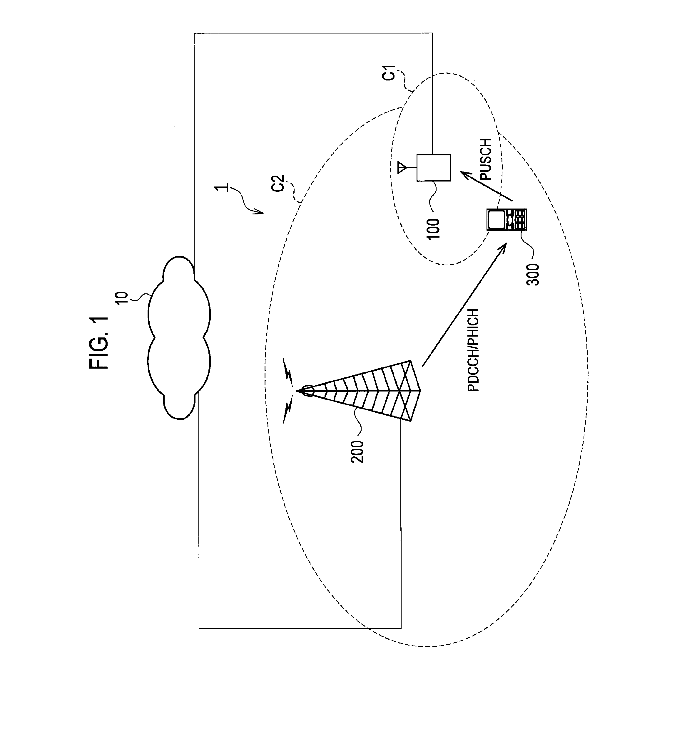
[0039]FIG. 1 is an entire schematic configuration diagram of a radio communication system 1 according to the first embodiment. The radio communication system 1 has the configuration based on, for example, LTE (Long Term Evolution) Release 9 which is the 3.9th generation (3.9G) cellular radio communication system or the configuration based on LTE-Advanced which is positioned as the 4th generation (4G) cellular communication system. Hereinafter, the LTE Release 9 and LTE-Advanced are collectively referred to as LTE.
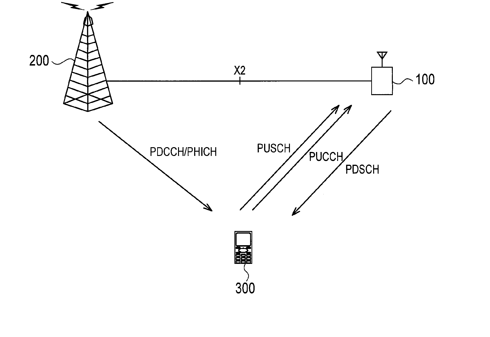
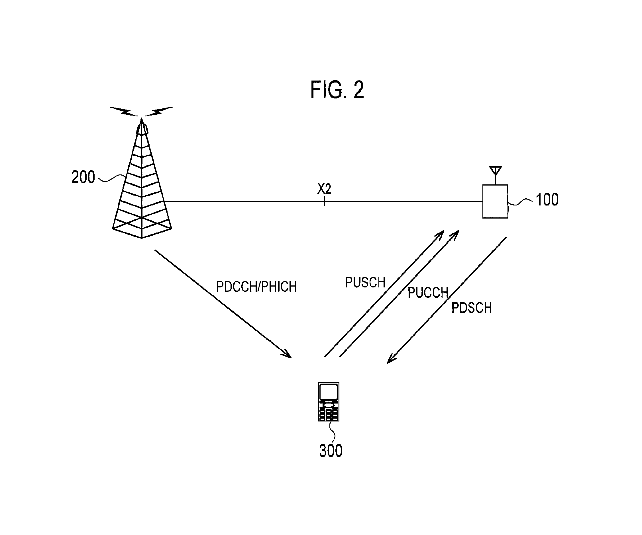
[0040]The radio communication system 1 has a low-power base station (a low-output power base station or a small-output base station) 100, a high-power base st...
second embodiment
Modification of Second Embodiment
[0124]Although the second embodiment is based on the assumption that the radio terminal 300 has only one connection destination, there is also a possibility that the radio terminal 300 can use multiple radio base stations as connection destinations and can simultaneously perform radio communications with the multiple radio base stations.
[0125]In the modification, an application execution unit 324 of the radio terminal 300 is made capable of simultaneously executing multiple applications. When detecting that the radio terminal 300 executes a real-time application and a non-real-time application, a handover controller 126 of the low-power base station 100 performs control to switch a connection destination of the radio terminal 300 which supports the real-time application to the high-power base station 200. In other words, the low-power base station 100 is maintained as being the connection destination of the radio terminal 300 which supports the non-r...
third embodiment
[0127]In the above-described embodiments, the high-power base station 200 transmits control information to the radio terminal 300 at the timing designated by the timing designation information received from the low-power base station 100. Also, at the designated timing, the low-power base station 100 transmits downlink user data to the radio terminal 300 or receives uplink user data transmitted from the radio terminal 300, and after specified sub-frames from the designated timing, receives ACK / NACK information of the downlink user data fed back from the radio terminal 300.
[0128]As described above, in the above-described embodiments, a timing difference since the low-power base station 100 transmits the control information to the high-power base station 200 until the high-power base station 200 transmits the control information to the radio terminal 300 is determined and designated by the low-power base station 100.
[0129]In a third embodiment, a timing difference since the low-power ...
PUM
 Abstract
Description
Claims
Application Information
 - R&D
- Intellectual Property
- Life Sciences
- Materials
- Tech Scout
- Unparalleled Data Quality
- Higher Quality Content
- 60% Fewer Hallucinations
Browse by: Latest US Patents, China's latest patents, Technical Efficacy Thesaurus, Application Domain, Technology Topic, Popular Technical Reports.
© 2025 PatSnap. All rights reserved.Legal|Privacy policy|Modern Slavery Act Transparency Statement|Sitemap|About US| Contact US: help@patsnap.com