Low pressure, low velocity steam injector

a low-pressure, injector technology, applied in the field of low-pressure, low-pressure steam injectors, can solve the problems of high pressure area outside the valve seat, steam pressure,

Inactive Publication Date: 2012-09-06
HORN DARRELL C +1
View PDF1 Cites 7 Cited by
  • Summary
  • Abstract
  • Description
  • Claims
  • Application Information

AI Technical Summary

Benefits of technology

[0027]It is a principal object and advantage of the present invention to reduce the required pressure of steam entering the injector needed to fully elevate and operate the valve head, while positively seating the valve head on the valve seat using a compression spring when steam pressure is absent.
[0028]To accomplish the forgoing objectives, the direct steam injector of the present invention is designed such that as steam flows into and through the injector, the steam loses pressure as it passes through steam transfer ports into an exhaust chamber under the valve head. This loss in steam pressure as steam flows through the steam transfer ports creates a high pressure area outside of the valve seat relative to the steam pressure in the exhaust chamber.
[0029]These operating advantages are achieved by providing a valve body having a novel pressure piston integral with the valve stem and disposed in an upper portion of the cylinder (or through bore) into which the valve stem is slidably disposed. The pressure piston has close clearances to optimize the driving force provided by the steam allowed to enter the upper portion of the cylinder below the pressure piston. Thus, as steam flows into the injector housing the higher pressure outside the valve seat is transferred to the underside of the pressure piston. Because the pressure under the pressure piston is higher than the pressure above the piston and in the exhaust chamber, the pressure under the piston will act with the pressure under the valve head to raise the valve at a steam pressure in the exhaust chamber lower than would be required in conventional direct steam injectors.
[0030]Further, the steam pressure in the exhaust chamber needed to fully raise the valve (and thus the steam velocity exiting from the injector into the product) can be reduced as much as desired simply by reducing the diameter of the steam transfer holes in the valve seat.
[0031]Other features, objects, and advantages of the invention will be described in the detailed description of the preferred embodiments of the invention which will form the subject matter of the claims appended hereto.BRIEF DESCRIPTION OF SEVERAL VIEWS OF THE DRAWINGS
[0032]The invention will be better understood and objects other than those set forth above will become apparent when consideration is given to the following detailed description thereof. Such description makes reference to the annexed drawings wherein:

Problems solved by technology

This loss in steam pressure as steam flows through the steam transfer ports creates a high pressure area outside of the valve seat relative to the steam pressure in the exhaust chamber.

Method used


Image

  • Low pressure, low velocity steam injector
  • Low pressure, low velocity steam injector
  • Low pressure, low velocity steam injector

Examples


Embodiment Construction

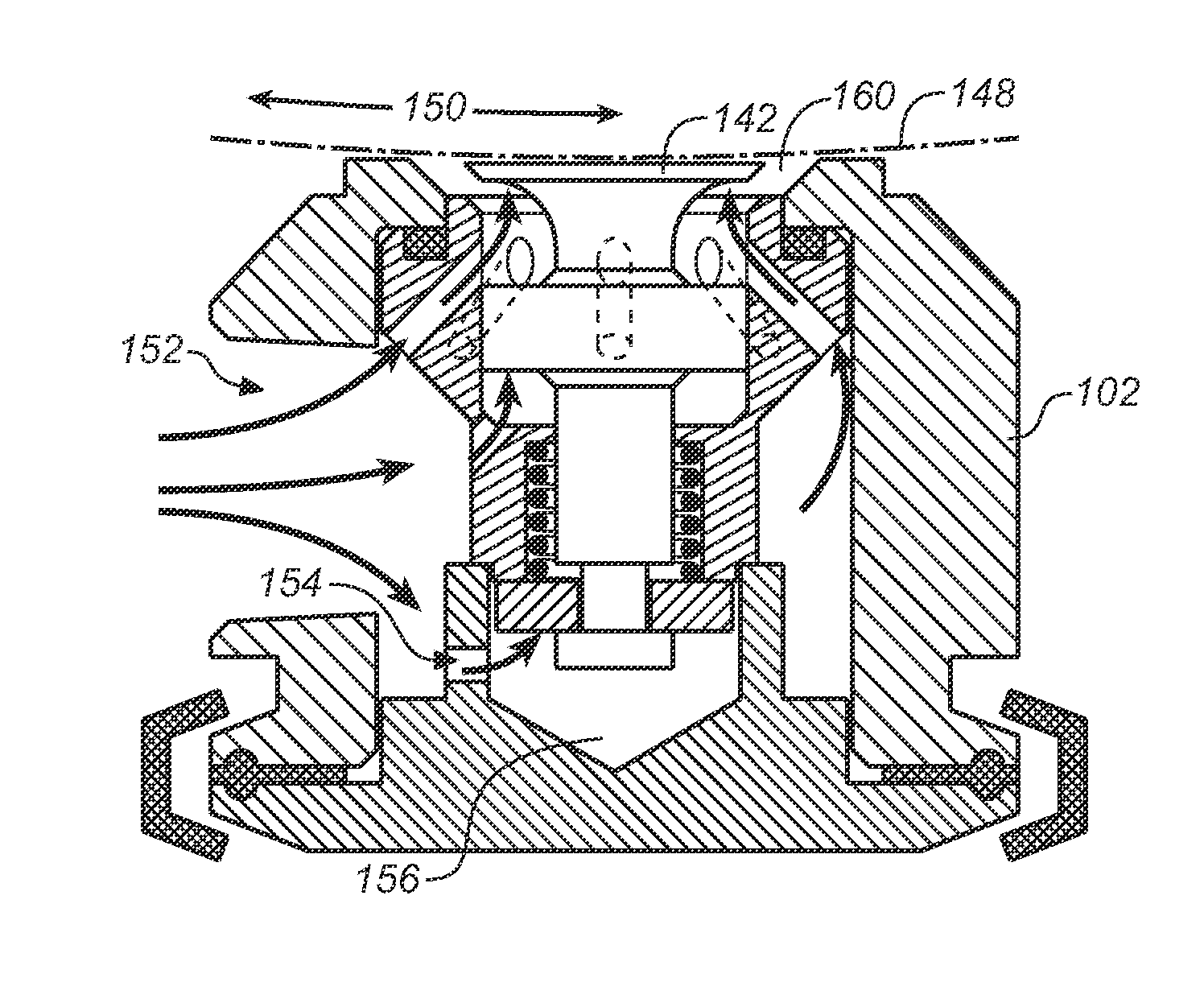
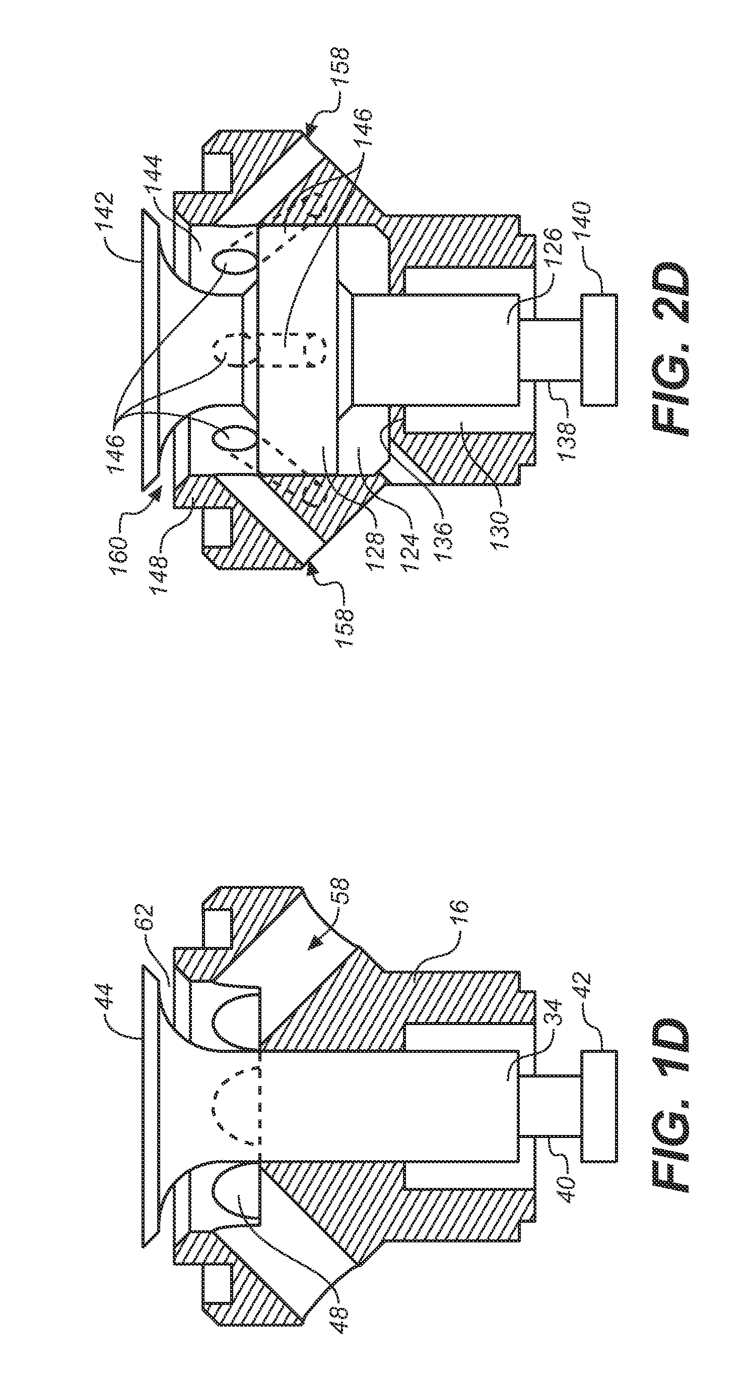
[0041]Referring to FIGS. 2A through 2D, wherein like reference numerals refer to like components in the various views, there is illustrated therein a new and improved low pressure, low velocity steam injector, generally denominated 100 herein. The drawings are described using terminology corresponding to the upright orientation of the steam injector, as shown. Accordingly, to the extent that a term such as “above” or “below” is used, it is for purposes of identifying an element or feature under discussion and better appreciating its structural or operational relationship to other features or elements.

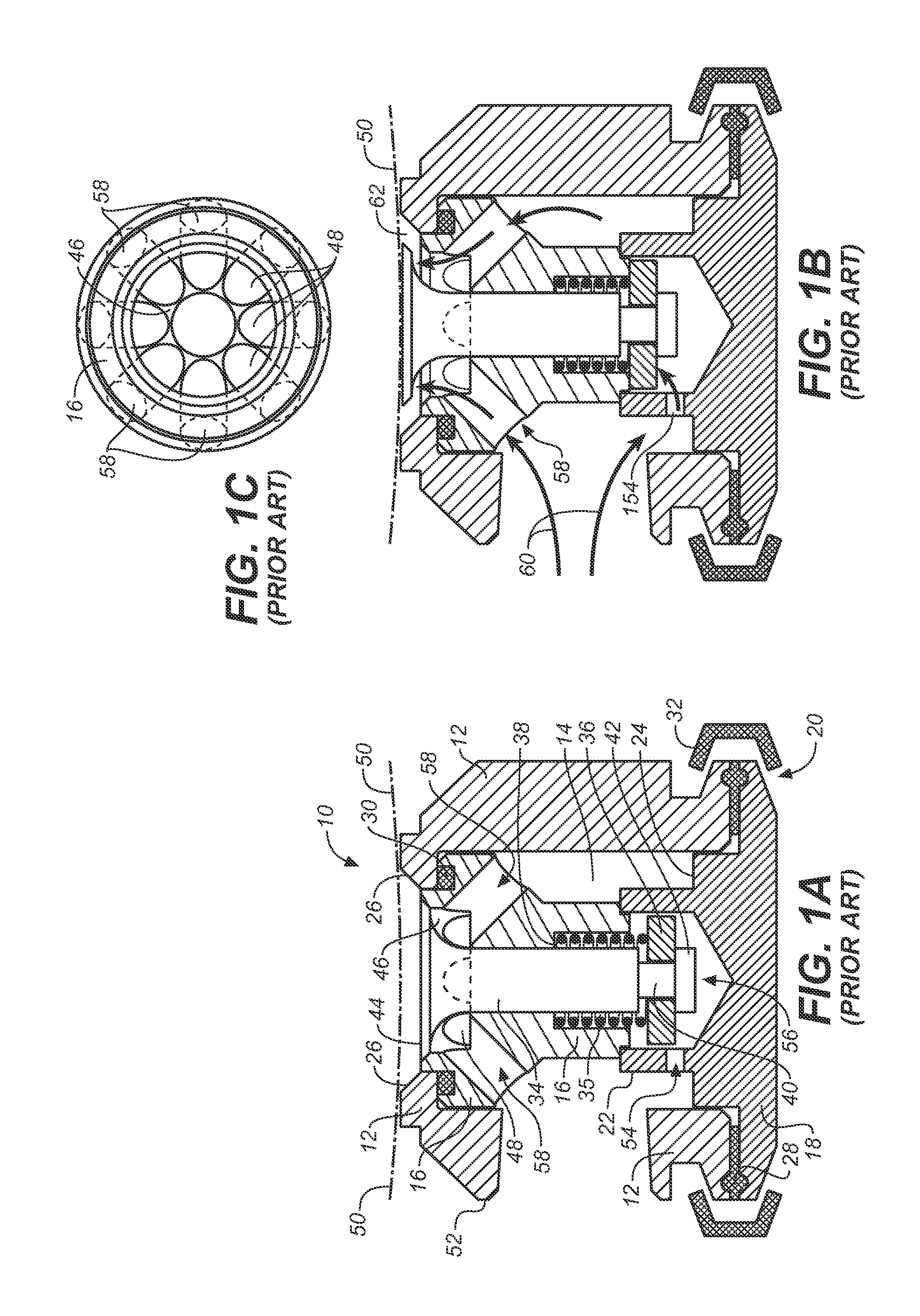
[0042]In several respects, the improved direct steam injector of the present invention resembles the prior art injector described in the preceding paragraphs and illustrated in FIGS. 1A-1D. For instance, the inventive steam injector includes a cylinder housing 102 having an interior void 104 in which a valve seat 106 is disposed. An end cap 108 is placed over a lower open end 110 of the...


PUM


Abstract

A direct steam injector for use in cooking food products by injecting live steam directly into the product to heat the food to cook temperatures. The injector operates under relatively low source steam manifold pressure while urging the valve return spring wide open, thus reducing the pressure of the steam flowing into the product. In addition to reducing the pressure of the steam, the steam injector reduces the velocity of the steam and better distributes it as the steam exits the injector, thereby reducing damage to the food product.

Description

CROSS REFERENCES TO RELATED APPLICATIONS[0001]The present application claims the benefit of U.S. Provisional Patent Application Ser. No. 61 / 464,268, filed Mar. 1, 2011 (Mar. 1, 2011).STATEMENT REGARDING FEDERALLY SPONSORED RESEARCH OR DEVELOPMENT[0002]Not applicable.THE NAMES OR PARTIES TO A JOINT RESEARCH AGREEMENT[0003]Not applicable.INCORPORATION BY REFERENCE OF MATERIAL SUBMITTED ON A COMPACT DISC[0004]Not applicable.BACKGROUND OF THE INVENTION[0005]1. Field of the Invention[0006]The present invention relates most generally to steam injectors, and more particularly to steam injectors for use in food cooking apparatus, and still more particularly to a low pressure, low velocity steam injector for use in live steam injection food cooking systems.[0007]2. Background Discussion[0008]It is commonly known that injecting live steam into food products is a more efficient method of cooking than indirect steam heating. Even so, this method of cooking is not currently used as much as indir...

Claims


Application Information

Patent Timeline
Patent Type & Authority Applications(United States)
IPC IPC(8): A47J36/00
CPCA47J27/04
Inventor HORN, DARRELL C.LENNOX, III, JOHN M.
Owner HORN DARRELL C
Why Eureka
Try Eureka