Rolling bearing, throttle valve device and abs device
- Summary
- Abstract
- Description
- Claims
- Application Information
AI Technical Summary
Benefits of technology
Problems solved by technology
Method used
Image

Examples
first embodiment
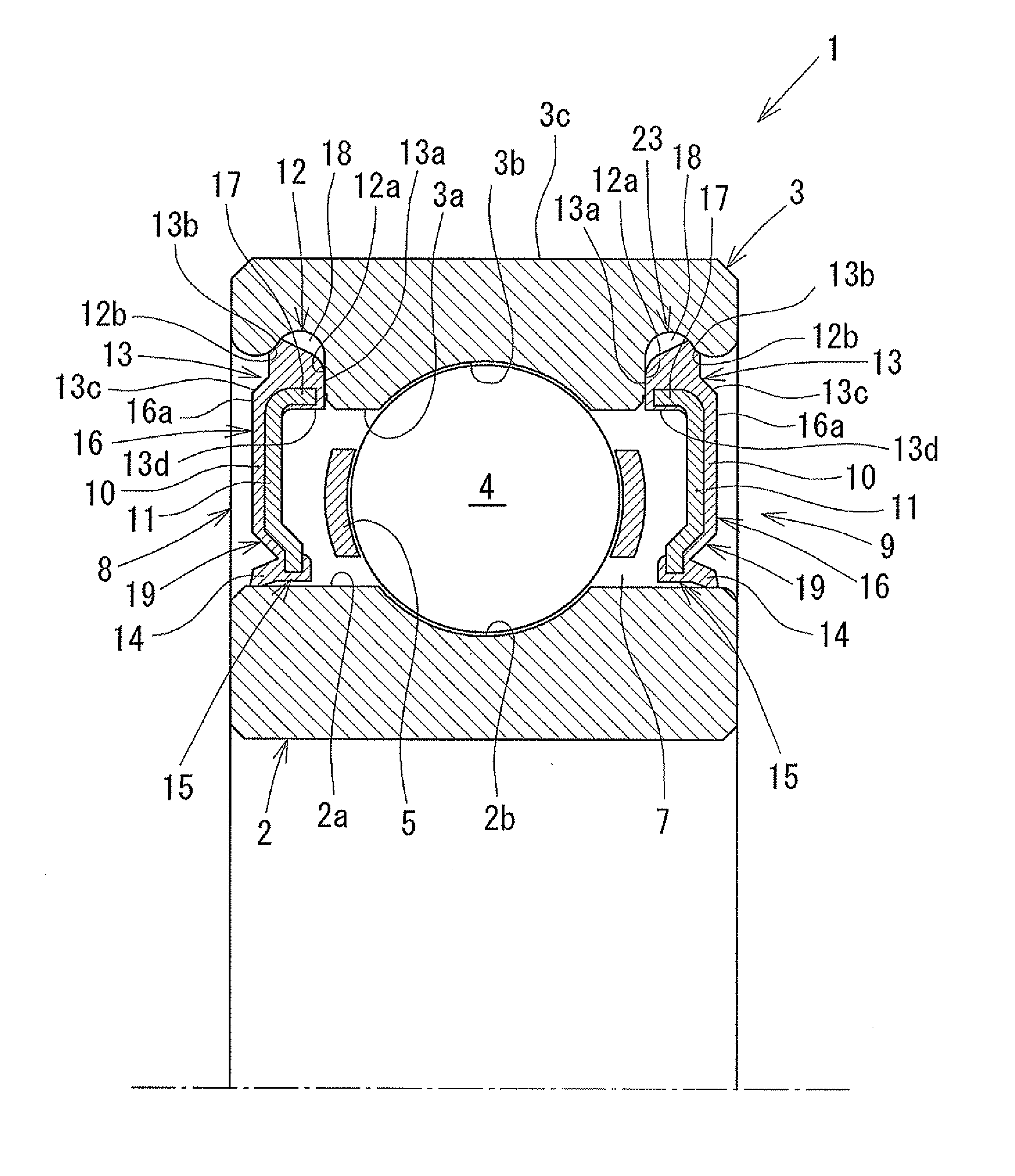
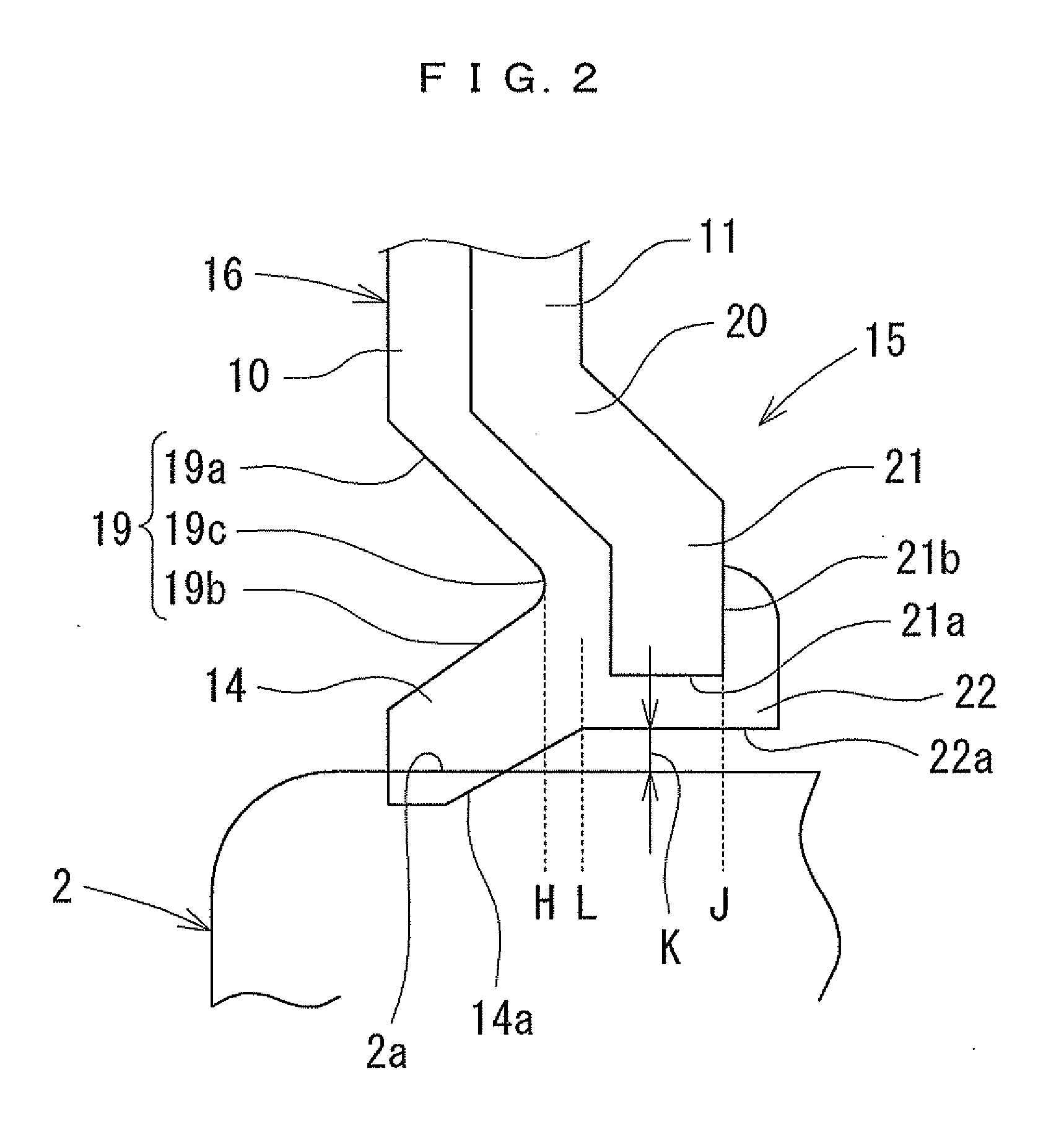
[0023]The first embodiment of the present invention will be described with reference to the accompanying drawings. In the following description, a central axis means the rotational axis (centerline) of a rolling bearing 1 which extends in a horizontal direction in FIG. 1, an axial plane means a plane which includes the central axis, and a transverse plane means a plane which is perpendicular to the central axis.
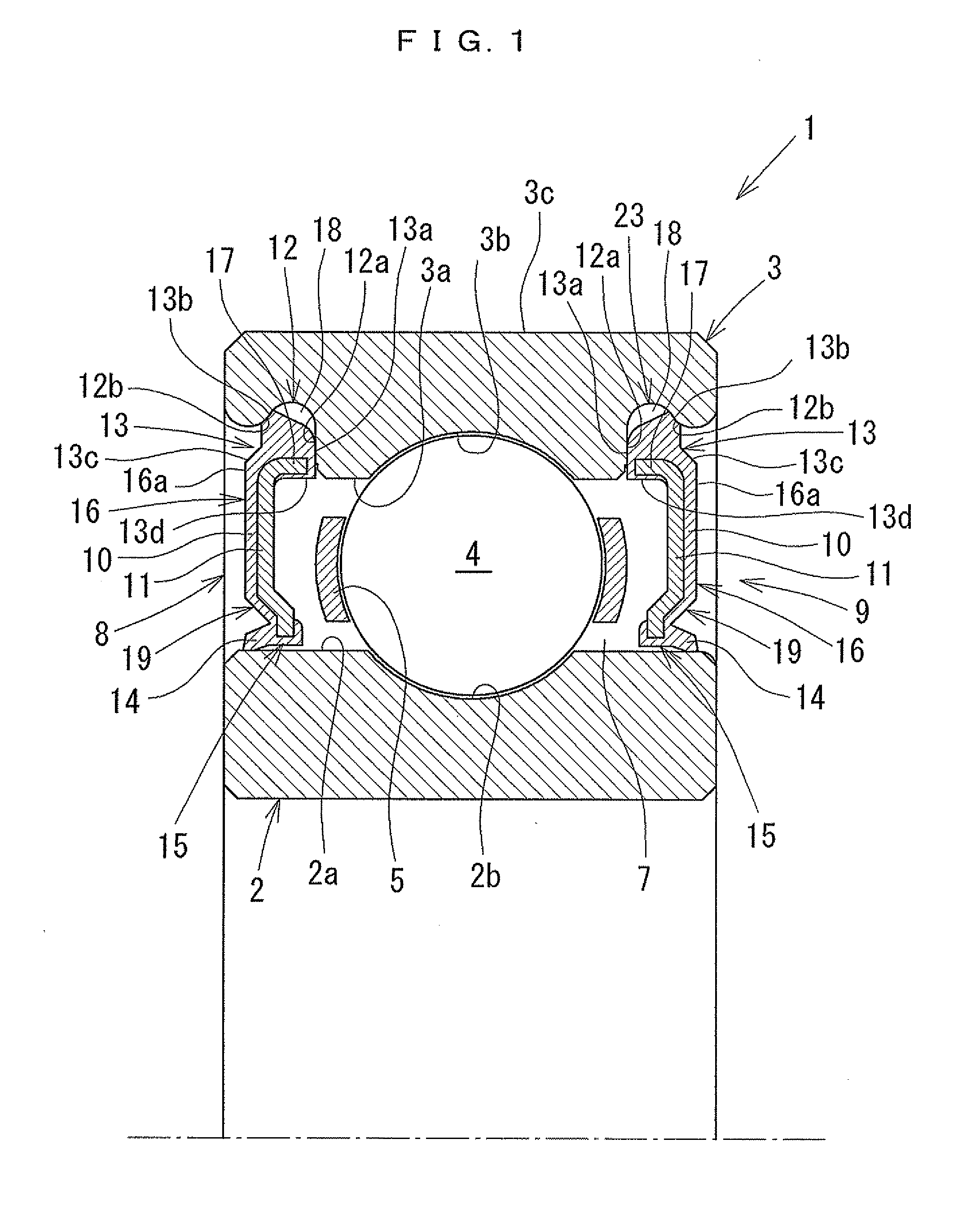
[0024]FIG. 1 is a cross-sectional view of the rolling bearing 1 according to the first embodiment on the axial plane. As illustrated in FIG. 1, the rolling bearing 1 includes an inner ring 2, an outer ring 3, a plurality of rolling elements 4 (steel balls) retained between an inner raceway 2b of the inner ring 2 and an outer raceway 3b of the outer ring 3, a retainer 5 which holds the rolling elements 4 at a predetermined interval on the raceways 2b and 3b, and a pair of sealing members 8 and 9 which are disposed to face each other in a central axis direction (horizontal dire...
second embodiment
[0062]The second embodiment of the present invention will be described with reference to the accompanying drawings. FIGS. 10 and 11 illustrate an embodiment where the rolling bearing 1 according to the first embodiment is applied to a throttle valve device 61 of an internal combustion engine. The same names and reference numerals are given to the same components as those of the first embodiment.
[0063]In the throttle valve device 61, a throttle valve 64 is fixed to a throttle shaft 63 passing through an air intake passage 62 in a diameter direction (horizontal direction in FIG. 10) and both ends of the throttle shaft 63 are supported by the rolling bearing 1. The outer ring 3 of each rolling bearing 1 is fitted into a fitting groove 12 of a housing 65. Since the configuration other than the rolling bearing 1 is the same as that of a conventional throttle valve device, the detailed description of the throttle valve device 61 will not be repeated in order to simplify the description of...
third embodiment
[0068]The third embodiment of the present invention will be described with reference to the accompanying drawings. FIG. 12 illustrates an embodiment where the rolling bearing 1 according to the first embodiment is applied to an ABS device 71 of a vehicle. The same components as those of the first embodiment will be referred with the same names and reference numerals as in the first embodiment.
[0069]The ABS device 71 includes a piston 72 which pumps a brake fluid in a reservoir tank and supplies the brake fluid to a master cylinder of the brake system and an electric motor 73 which moves the piston 72 for driving the ABS pump. A driving shaft 74 of the electric motor 73 is supported by a pair of rolling bearings 1 mounted to a motor housing 75. Since the configuration of the ABS device 71 is the same as that of a conventional ABS device except the rolling bearing 1, the detailed description of the ABS device 71 will be omitted in order to simplify the description.
[0070]Next, the acti...
PUM
 Abstract
Description
Claims
Application Information
 - R&D
- Intellectual Property
- Life Sciences
- Materials
- Tech Scout
- Unparalleled Data Quality
- Higher Quality Content
- 60% Fewer Hallucinations
Browse by: Latest US Patents, China's latest patents, Technical Efficacy Thesaurus, Application Domain, Technology Topic, Popular Technical Reports.
© 2025 PatSnap. All rights reserved.Legal|Privacy policy|Modern Slavery Act Transparency Statement|Sitemap|About US| Contact US: help@patsnap.com