
MEMS Sensor with Movable Z-Axis Sensing Element

Active Publication Date: 2012-09-06
ANALOG DEVICES INC
View PDF1 Cites 34 Cited by
  • Summary
  • Abstract
  • Description
  • Claims
  • Application Information

AI Technical Summary

Problems solved by technology

However, parasitic capacitance between the electrode and the substrate may undesirably impact the reliability of this measurement.

Method used


Image

  • MEMS Sensor with Movable Z-Axis Sensing Element
  • MEMS Sensor with Movable Z-Axis Sensing Element
  • MEMS Sensor with Movable Z-Axis Sensing Element

Examples


Embodiment Construction

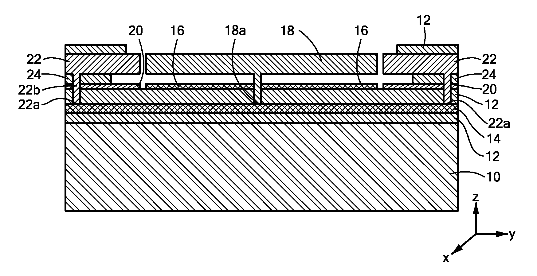
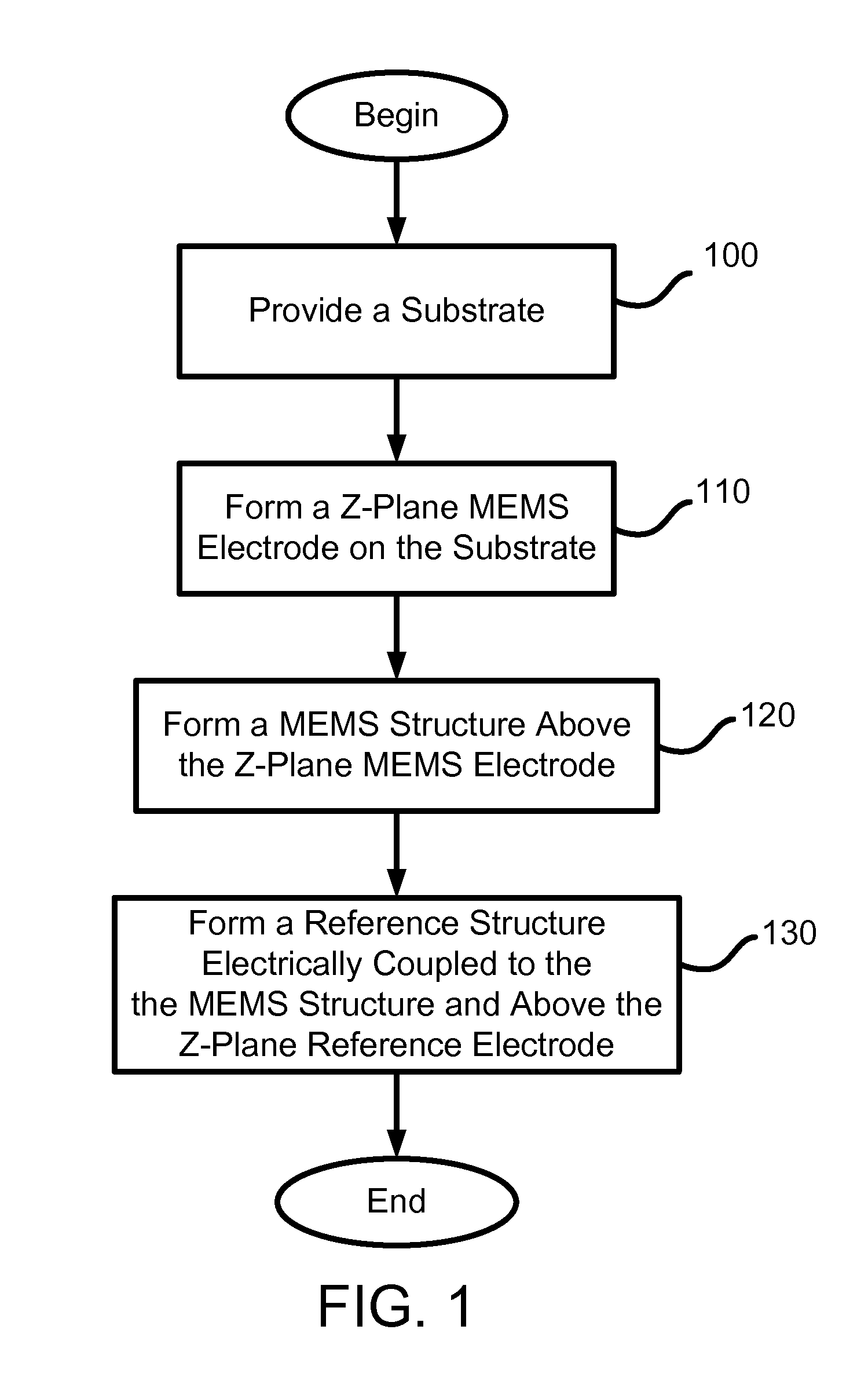
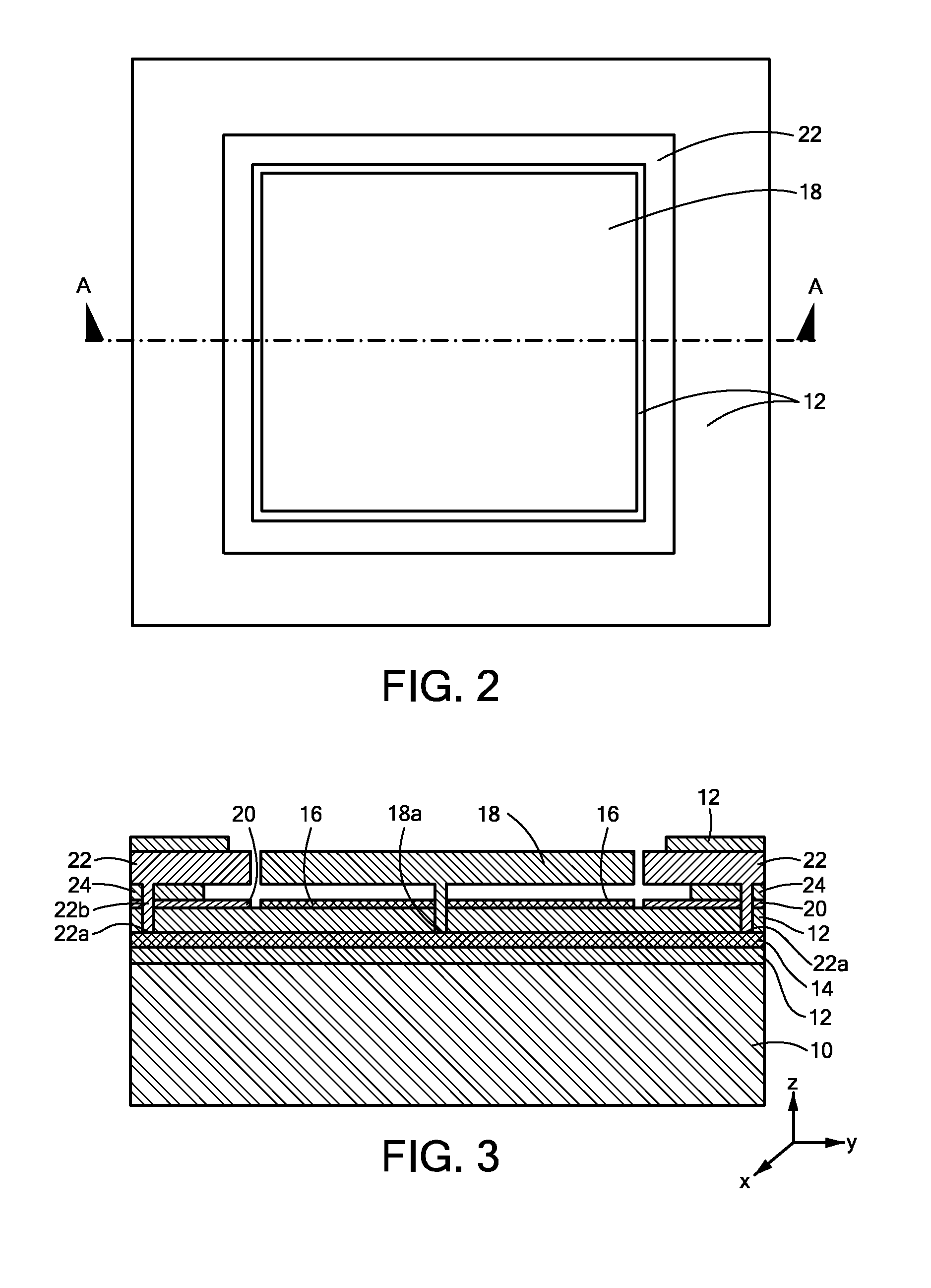
[0005]In accordance with one embodiment of the invention, a MEMS sensor includes a substrate and a MEMS structure coupled to the substrate. The MEMS structure has a mass movable with respect to the substrate. The MEMS sensor also includes a reference structure electrically coupled to the movable mass of the MEMS structure.

[0006]In accordance with related embodiments, the reference structure may substantially circumscribe the MEMS structure or the MEMS structure may substantially circumscribe the reference structure. One surface of the reference structure may be substantially coplanar with one surface of the MEMS structure. The MEMS structure may be radially outward from the reference structure. The MEMS sensor may further include a z-plane MEMS electrode formed on the substrate. The z-plane MEMS electrode may be formed substantially beneath the MEMS structure. The MEMS sensor may further include a z-plane reference electrode formed on the substrate and coplanar with the z-plane MEMS...


PUM


Abstract

A MEMS sensor includes a substrate and a MEMS structure coupled to the substrate. The MEMS structure has a mass movable with respect to the substrate. The MEMS sensor also includes a reference structure electrically coupled to the mass of the MEMS sensor. The reference structure is used to provide a reference to offset any environmental changes that may affect the MEMS sensor in order to increase the accuracy of its measurement.

Description

CROSS-REFERENCE TO RELATED APPLICATIONS[0001]The present application is a continuation-in-part of U.S. patent application Ser. No. 12 / 205,241 filed Sep. 5, 2008, the disclosure of which is incorporated by reference herein in its entirety.TECHNICAL FIELD[0002]The invention generally relates to sensing elements for MEMS sensors and, more particularly, the invention relates to a movable sensing element for measuring z-axis movement in MEMS sensors.BACKGROUND ART[0003]Sensors employing microelectromechanical systems (MEMS) devices are increasingly used in different applications to detect the movement of an underlying object or the presence of a substance or condition due to their relatively small size and their capability to detect relatively small amounts or changes in the measured item. MEMS devices typically employ a movable, inertial mass or flexible membrane formed with one or more fixed, non-moving structures or fingers. For example, in a MEMS accelerometer, the inertial mass may ...

Claims


Application Information

Patent Timeline
IPC IPC(8): G01R27/26H01L21/02H01L29/84
CPCB81B3/0051B81B2203/053G01P15/0802G01P2015/0871G01P15/18G01P21/00G01P15/125
Inventor ZHANG, XINJUDY, MICHAEL W.
Owner ANALOG DEVICES INC
Learn More