Imager reader with hand gesture interface

a technology of imager reader and indicia, which is applied in the field of imager-based indicia reading terminals, can solve the problems of cumbersome and time-consuming current reconfiguration methods, customer dissatisfaction, etc., and achieve the effect of quick switching of the mode of operation

Inactive Publication Date: 2012-09-06
HAND HELD PRODS
View PDF8 Cites 28 Cited by
  • Summary
  • Abstract
  • Description
  • Claims
  • Application Information

AI Technical Summary

Benefits of technology

[0008]Accordingly, there is a need for an imager that can quickly switch its mode of operation without complicated steps or additional hardware. In ones aspect of the invention, provided herein is a system for decoding an encoded symbol character associated with a product. The system includes an imager-based indicia reading terminal comprising a housing and a two-dimensional image sensor array and an imaging lens for focusing an image on the two-dimensional image sensor array. The terminal is adapted to read an encoded symbol character, and further adapted to image a hand gesture. The terminal includes a digital link to transmit the image of the hand gesture. The system further includes a memory coupled to the indicia reading terminal via a digital connection. The memory includes a hand gesture attribute library to associate predefined hand gestures with a terminal mode of operation. The system further includes a central processing unit connected to the digital link to receive the image of the hand gesture, correlate the image with the predefined hand gestures in the hand gesture attribute library, and execute the associated terminal mode of operation.

Problems solved by technology

One drawback to this approach is that this method often requires that the end user have available the relevant programming barcodes.
The end user must search the manual to find the programming barcode for the desired configuration, which wastes time, may result in erroneous entry, and could lead to customer dissatisfaction.
In those circumstances where the end user wishes to change the configuration of the imager for a short duration or one-time use, the current reconfiguration methods are cumbersome and time-consuming.

Method used


Image

  • Imager reader with hand gesture interface
  • Imager reader with hand gesture interface
  • Imager reader with hand gesture interface

Examples


Embodiment Construction

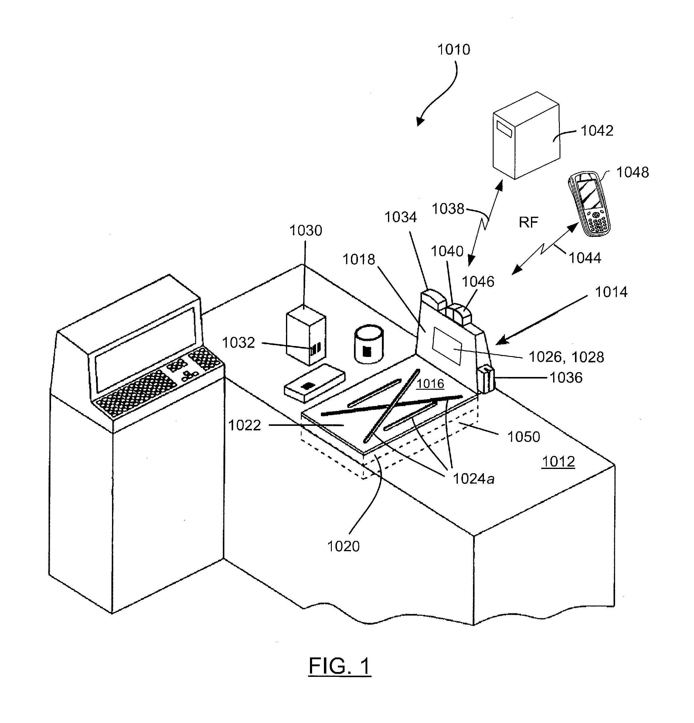
[0017]FIG. 1 illustrates a point-of-sale workstation 1010 used by retailers to process transactions involving the purchase of products bearing an encoded symbol character, typically a UPC symbol. The workstation 1010 includes a horizontal countertop 1012 for placement of products to be scanned. A bioptic scanner 1014 mounted within the countertop 1012 includes a first housing portion 1016 and a second housing portion 1018 which projects from one end of the first housing portion in a substantially orthogonal manner. When the bioptic scanner 1014 is installed within the countertop surface, the first housing portion 1016 is oriented horizontally, whereas the second housing portion 1018 is oriented vertically with respect to the point-of-sale (POS) station. Thus, as referred to herein, the terms ‘first housing portion’ and ‘horizontally-disposed housing portion’ may be used interchangeably but refer to the same structure. Likewise, the terms ‘second housing portion’ and ‘vertically-disp...


PUM


Abstract

A system for decoding an encoded symbol character associated with a product is provided herein. The system includes an imager-based indicia reading terminal comprising a housing and a two-dimensional image sensor array and an imaging lens for focusing an image on the two-dimensional image sensor array. The terminal is adapted to read an encoded symbol character, and further adapted to image a hand gesture. The terminal includes a digital link to transmit the image of the hand gesture. The system further includes a memory coupled to the indicia reading terminal via a digital connection. The memory includes a hand gesture attribute library to associate predefined hand gestures with a terminal mode of operation. The system further includes a central processing unit connected to the digital link to receive the image of the hand gesture, correlate the image with the predefined hand gestures in the hand gesture attribute library, and execute the associated terminal mode of operation.

Description

FIELD OF THE INVENTION[0001]This disclosure relates generally to imager-based indicia reading terminals and, more specifically, to embodiments of indicia reading terminals that are configured to execute changes in modes of operation using hand gestures.BACKGROUND OF THE INVENTION[0002]The use of optical indicia, such as barcode symbols, for product and article identification is well known in the art. Presently, various types of indicia reading terminals have been developed, such as hand-held barcode scanners, hands-free scanners, bioptic in-counter scanners, and mobile computers such as personal digital assistants (PDAs). One common type of scan engine found in hand-held and retail scanners is the laser-based scan engine, which uses a focused laser beam to sequentially scan the bars and spaces of a barcode symbol pattern to be read. The majority of laser scanners in use today, particular in retail environments, employ lenses and moving (e.g., rotating or oscillating) mirrors and / or ...

Claims


Application Information

Patent Timeline
Patent Type & Authority Applications(United States)
IPC IPC(8): H04N7/18
CPCG06K7/1091G06K7/10881
Inventor WANG, YNJIUN P.
Owner HAND HELD PRODS
Why Eureka
Try Eureka