Suspension wire for compensating for hand vibration and image photographing device having the same

a technology of hand vibration and suspension wire, which is applied in the direction of television systems, instruments, printing, etc., can solve the problems of deteriorating image quality, affecting the performance affecting the so as to prevent and minimize permanent deformation or facture, improve the performance and accuracy of hand vibration compensation and improve the effect of auto-focusing of the image photographing devi

Active Publication Date: 2012-09-06
SAMSUNG ELECTRO MECHANICS CO LTD
View PDF4 Cites 30 Cited by
  • Summary
  • Abstract
  • Description
  • Claims
  • Application Information

AI Technical Summary

Benefits of technology

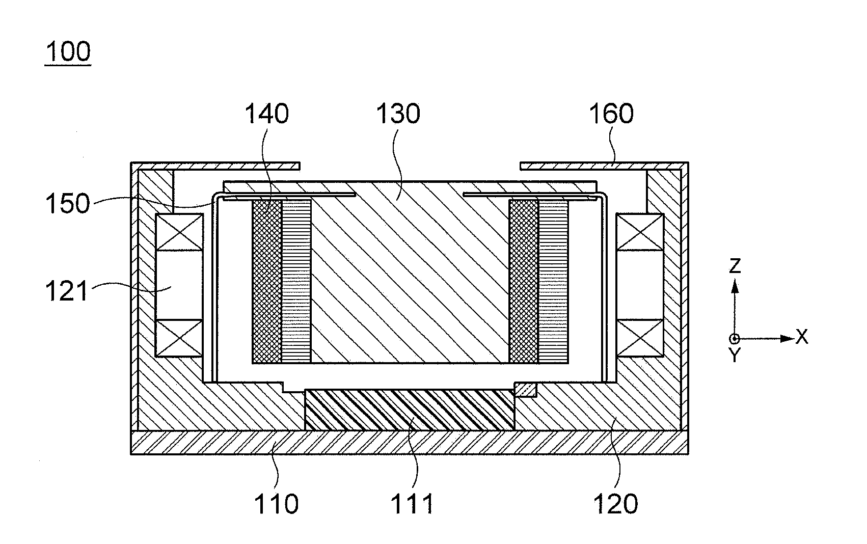
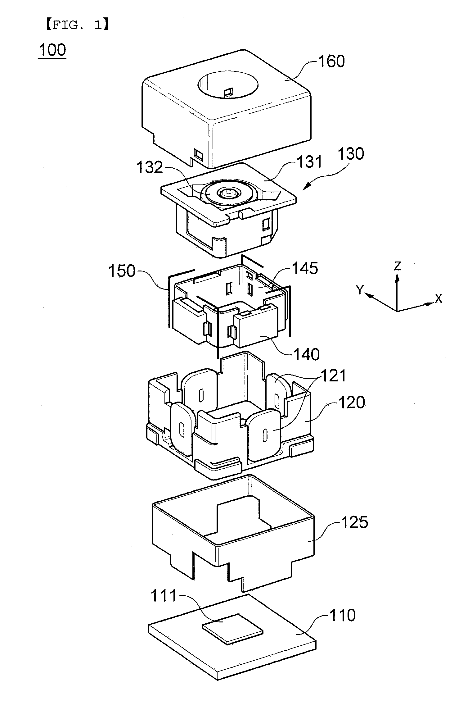
[0018]An object of the present invention is to provide a suspension wire for compensating for hand vibration in which a deformation buffer is formed in a wire body supporting an optical unit to prevent and minimize permanent deformation or facture of the suspension wire due to external impact while ...

Problems solved by technology

As the number of pixels of the camera module is increased, the size of the pixel becomes small and the receiving sensitivity of the light photographed in the image sensor becomes sensitive, and the image photographed in the image sensor is out of focus even with small hand vibration when operating a shutter of the camera or the mobile device, such that image quality is deteriorated.
Therefore, it is impossible to obtain a sharp photograph.
The deterioration of the image quality due to the hand vibration is generated because the light passing through the lens of the optical system is out of the optical axis of the lens.
Here, when the lens is moved along the two-axis guide, compensation performance may be deteriorated due to the friction between the two-axis guide and the lens, and when the two-axis guide and the lens are moved or the two-axis guide is moved, noise or foreign materials may occur due to the friction with other components.
In addition, since the two-axis guide supports the periphery of the lens, the size of the camera module cannot but be enlarged by a space in which the two-axi...

Method used


Image

  • Suspension wire for compensating for hand vibration and image photographing device having the same
  • Suspension wire for compensating for hand vibration and image photographing device having the same
  • Suspension wire for compensating for hand vibration and image photographing device having the same

Examples


first embodiment

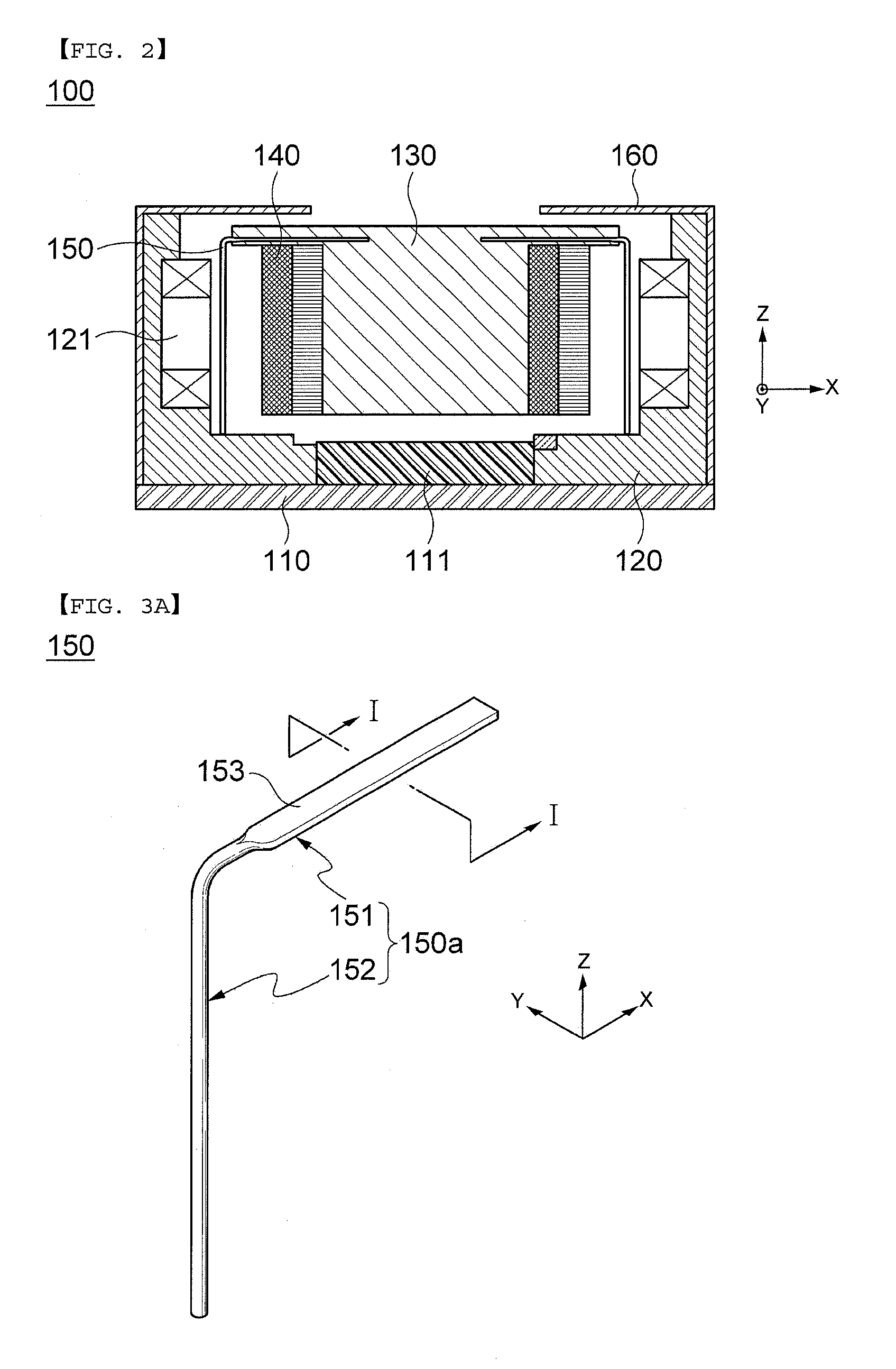
[0078]Similar to the first embodiment, in the suspension wire 250 according to the present embodiment, the wire body 250a is formed to have a circular cross section or a square cross section, and the deformation buffer 253 has a cross-sectional shape different from that of the wire body 250a, for example, a cross-sectional shape in which a width b is larger than a height h, while being maintained to have the same cross-sectional area as that of the wire body 250a. Therefore, the warpage deformation is minimized during the bending operation through the impact force, that is, the tensile force or the compressive force, acting on the suspension wire 250 in the optical axis direction Z, thereby making it possible to prevent or minimize permanent deformation or fracture of the suspension wire 250 due to external impact.

[0079]In addition, in the suspension wire 250 according to the present embodiment, the deformation buffer 253 is formed to be extended to the bent portion, thereby making ...

third embodiment

[0080]FIG. 6 is a perspective view schematically showing a suspension wire according to the present invention. As shown in FIG. 6, a suspension wire 350 according to the present embodiment is formed in a bent shape in which a wire body 350a includes a horizontal wire body 351 and a vertical wire body 352, and includes a deformation buffer 354 formed in the vertical wire body 352.

[0081]Here, the deformation buffer 354 may include a first vertical deformation buffer 354a and a second vertical deformation buffer 345b each formed in an upper portion and a lower portion of the vertical wire body 352.

[0082]In this configuration, the first vertical deformation buffer 354a and the second vertical deformation buffer 345b may be formed to have cross sections that are rotationally symmetrical to each other by 90 degrees, thereby making it possible to elastically move the vertical wire body 352 in the directions perpendicular to the optical axis direction Z, that is, the hand vibration compensa...

fifth embodiment

[0094]FIG. 8 is a perspective view schematically showing a suspension wire for compensating for hand vibration according to the present invention. A suspension wire 550 according to the present embodiment is formed in a bent shape in which a wire body 550a includes a horizontal wire body 551 and a vertical wire body 552, and includes deformation buffers 553 and 554 formed in the horizontal wire body 551 and the vertical wire body 552.

[0095]That is, the deformation buffers 553 and 554 according to the present embodiment may include a horizontal deformation buffer 553 formed in the horizontal wire body 551 and a vertical deformation buffer 554 formed in the vertical wire body 552.

[0096]In this configuration, the horizontal deformation buffer 553 and the vertical deformation buffer 554 may be formed to have cross sections that are rotationally symmetrical to each other by 90 degrees. That is, the horizontal deformation buffer 553 may be formed to have a cross section in a rectangular f...


PUM


Abstract

Disclosed herein are a suspension wire for compensating for hand vibration and an image photographing device having the same. The suspension wire for compensating for hand vibration, which is mounted between an optical unit and a housing so as to have a length thereof in an optical axis direction to float and support the optical unit within the housing, includes: a wire body having both ends thereof each fixed to the optical unit and the housing; and a deformation buffer formed in the wire body to allow the wire body to flexibly receive impact force when external impact is applied to the wire body, thereby preventing permanent deformation or fracture of the wire body.

Description

CROSS REFERENCE(S) TO RELATED APPLICATIONS[0001]This application claims the benefit under 35 U.S.C. Section 119 of Korean Patent Application Serial No. 10-2011-0018486, entitled “Suspension Wire For Compensating For Hand Vibration And Image Photographing Device Having The Same” filed on Mar. 2, 2011, which is hereby incorporated by reference in its entirety into this application.BACKGROUND OF THE INVENTION[0002]1. Technical Field[0003]The present invention relates to a suspension wire for compensating for hand vibration and an image photographing device having the same, and more particularly, to a suspension wire for compensating for hand vibration in which a shape and a supporting structure of the suspension wire supporting an optical unit are changed to prevent permanent deformation or fracture of the suspension wire due to external impact, and an image photographing device having the same.[0004]2. Description of the Related Art[0005]Recently, use of a subminiature camera module f...

Claims


Application Information

Patent Timeline
IPC IPC(8): H04N5/225
CPCG02B27/646G03B17/02G03B5/02G02B7/026G03B30/00G03B2205/0007
Inventor LIM, SOO CHEOLON, SANG MINKANG, BYUNG WOO
Owner SAMSUNG ELECTRO MECHANICS CO LTD
Why Eureka
Try Eureka