Compact fiber optic positioner with wide frequency bandwidth

a fiber optic positioner and fiber optic technology, applied in the field of compact fiber optic positioners with wide frequency bandwidth, can solve the problems of deterioration of performance of modem optical communication positioners designed for near-horizontal propagation of carrier laser beams, cumbersome positioning, and high speed of linear micro-motor positioners

Inactive Publication Date: 2012-09-06
US SEC THE ARMY THE
View PDF6 Cites 36 Cited by
  • Summary
  • Abstract
  • Description
  • Claims
  • Application Information

AI Technical Summary

Problems solved by technology

However, it is to be noted that these positioners are very cumbersome and have various issues with regard to fiber optic displacement.
For example, linear micro-motor positioners have problems moving the fiber output long distances with high speed.
Additionally, modem optical communication positioners designed for near-horizontal propagation of carrier laser beams suffer from degradation of performance due to atmospheric turbulences.
In particular, the degradation of the carrier beam is a result of fast fluctuating deviations of the beam from the “ideal line” connecting the laser transmitter and photo-receiver.
However, there is no data about embodiments and characteristics of the deviation amplitude of distal end of fiber as well as no data about the frequency bandwidth and resonant behavior.
Moreover, the is not suitable for two-dimensional steering of the fiber optic distal end.
However, it is problematic to consider this device for use in resonance-free fiber optic steering in wide frequency ranges, for instance exceeding 1 kHz, due to small stiffness of thin-film polymer-based piezoelectric material since the considerable deviations take place only at resonance conditions.
Further, it was stated that described device should have better resonance performance, than previously patented devices, however, there is no data about actual scanning ranges and resonance behavior discussed.
However, this device can not be used for high frequency bandwidth due to three basic restrictions: 1) Very small stiffness of PVDF films to provide high enough distal end displacement, so the resonance frequency could be 2-3 orders less than ceramic or crystal materials; 2) The passive damping of bending actuators require the installation of damping material, which will block the controlling light; and 3) In most fiber optic base systems, there is not enough space to introduce additional elements such as, for example LEDs, lenses, and wires.
However, the device is slow and is considered to compensate the disturbances of the laser beam propagation direction at low-frequency vibrations of mounts, building sway, etc.
Additionally, the device has unwieldy and fragile structure.
Therefore, it has been determined that there are no compact lightweight devices for two-dimensional positioning or steering fiber optics in kHz frequency bandwidth having a displacement of distances of roughly 100 microns or more.

Method used


Image

  • Compact fiber optic positioner with wide frequency bandwidth
  • Compact fiber optic positioner with wide frequency bandwidth
  • Compact fiber optic positioner with wide frequency bandwidth

Examples


Embodiment Construction

[0055]The embodiments herein and the various features and advantageous details thereof are explained more fully with reference to the non-limiting embodiments that are illustrated in the accompanying drawings and detailed in the following description. Descriptions of well-known components and processing techniques are omitted so as to not unnecessarily obscure the embodiments herein. The examples used herein are intended merely to facilitate an understanding of ways in which the embodiments herein may be practiced and to further enable those of skill in the art to practice the embodiments herein. Accordingly, the examples should not be construed as limiting the scope of the embodiments herein.

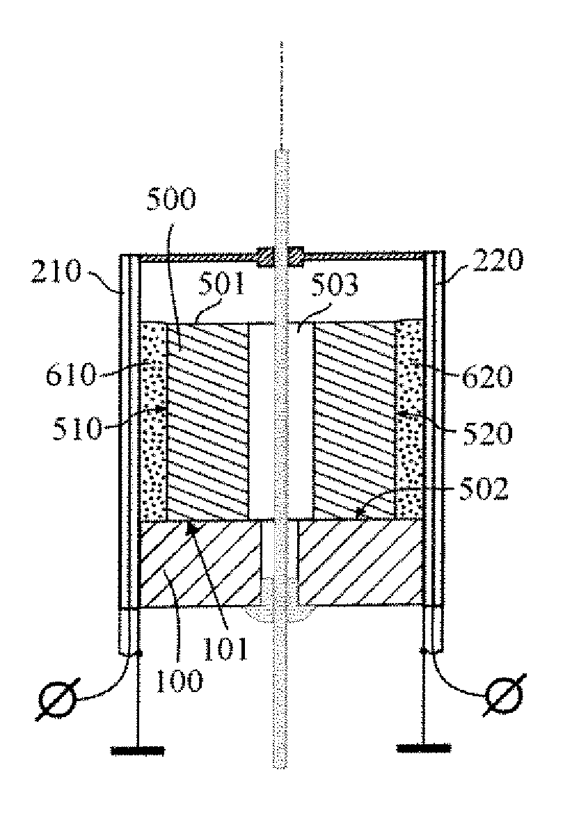
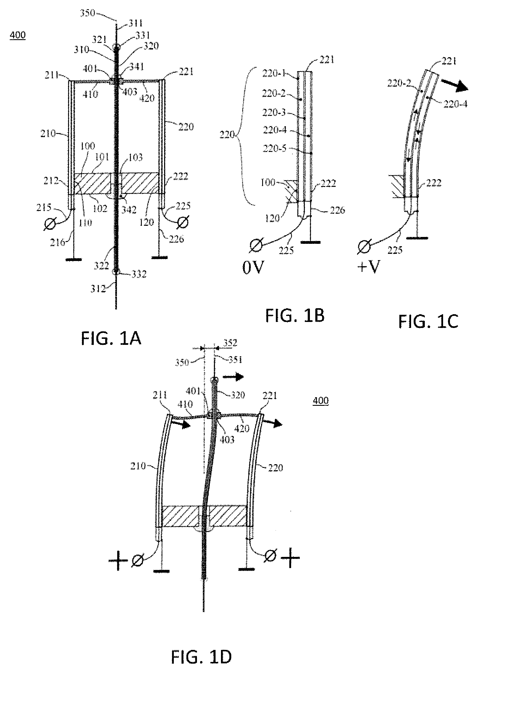
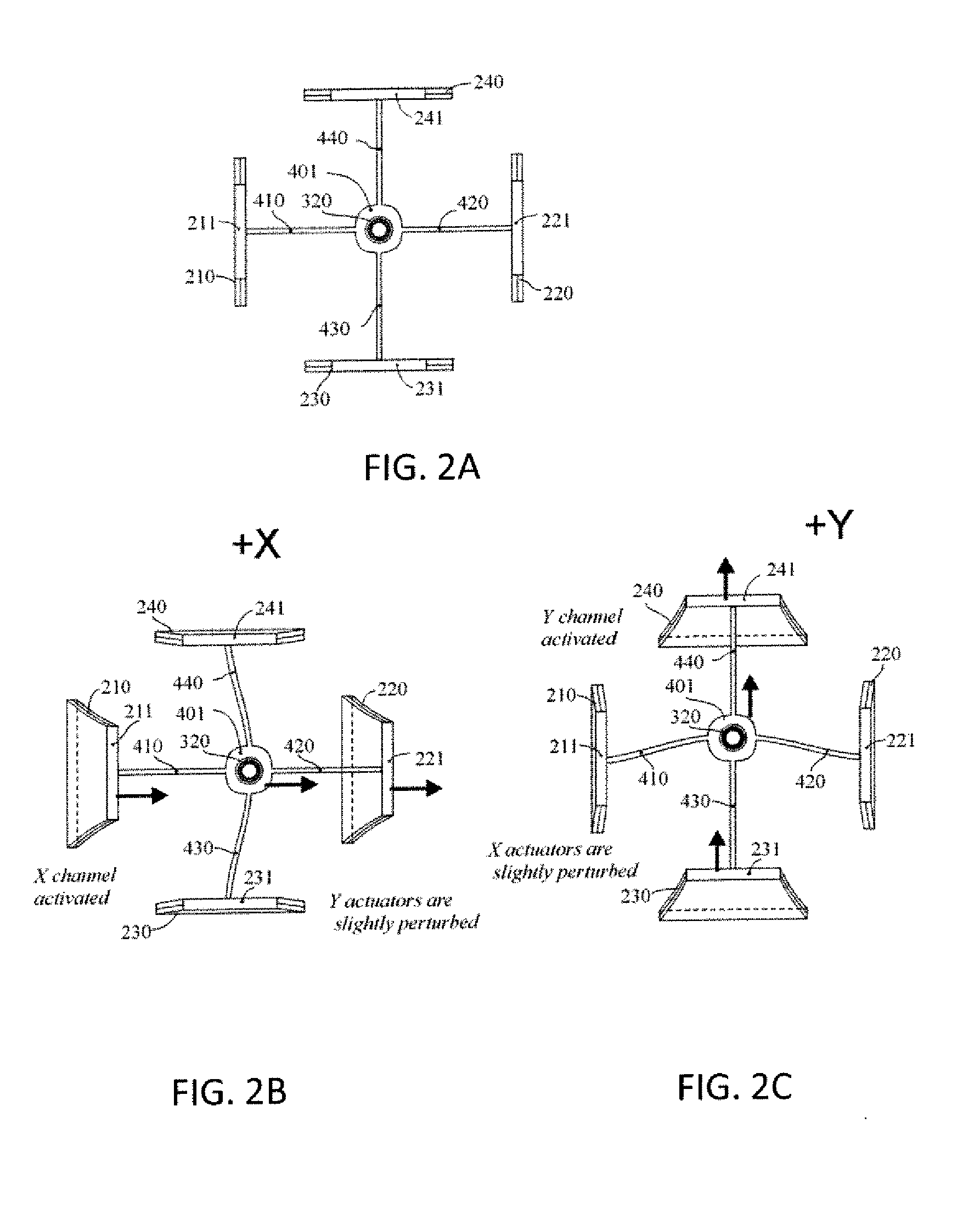
[0056]The embodiments described herein provide methods and devices that include fast two-dimensional steering or positioning of fiber optic outputs. More particularly, the embodiments described herein provide a fiber optic positioner that positions the ends of optical fiber in two dimensions by...


PUM


Abstract

A device for the positioning of fiber optic output including a base having a hole disposed at a midpoint thereof, a collar having an opening at a midpoint, a plurality of bimorph actuators, each actuator connected to an outer side surface of the base and located at opposite ends, a plurality of flexible beams, each having a first end connected to the collar and a second end connected to a bimorph actuator, a flexible tube inserted in the hole, where a bottom end of the tube is cantilevered at a bottom of the base and a top end of the tube is inserted in the opening of the collar, and a fiber optic embedded in the flexible tube.

Description

GOVERNMENT INTEREST[0001]The embodiments described herein may be manufactured, used, and / or licensed by or for the United States Government without the payment of royalties thereon.BACKGROUND[0002]1. Technical Field[0003]The embodiments described herein generally relate to methods and devices. More particularly, the embodiments herein relate to a positioning of fiber optic devices in predetermined directions.[0004]2. Description of the Related Art[0005]Fiber-optic communications are well known as methods of transmitting information from one place to another by sending pulses of light through an optical fiber. The light forms an electromagnetic carrier wave that is modulated to carry information. The positioning of the optical fiber output (i.e., the source of the pulses of light) is among the most common techniques in the fields utilizing the fiber optics. The static displacement of fiber optic output having high resolution can be accomplished utilizing numerous X, Y, Z types of pos...

Claims


Application Information

Patent Timeline
Patent Type & Authority Applications(United States)
IPC IPC(8): G02B6/00
CPCG02B6/4226
Inventor BERESNEV, LEONID A.VORONTSOV, MIKHAIL A.
Owner US SEC THE ARMY THE
Why Eureka
Try Eureka