Wear-Compensation Device For A Gear

a technology of wear-compensation device and gear, which is applied in the direction of gearing, gearing elements, toothed gearings, etc., can solve the problem of a large number of assembly operations

Active Publication Date: 2012-09-13
AB SKF
View PDF9 Cites 19 Cited by
  • Summary
  • Abstract
  • Description
  • Claims
  • Application Information

AI Technical Summary

Benefits of technology

[0006]The object of the present invention is to provide a mechanism to limit the phenomena of wear of the gear set over time.
[0009]More particularly, the object of the present invention is to provide a wear-compensation device for a gear easy to manufacture, to install, having a restricted space requirement and economic.

Problems solved by technology

This solution leads to a considerable number of assembly operations.

Method used


Image

  • Wear-Compensation Device For A Gear
  • Wear-Compensation Device For A Gear
  • Wear-Compensation Device For A Gear

Examples


Embodiment Construction

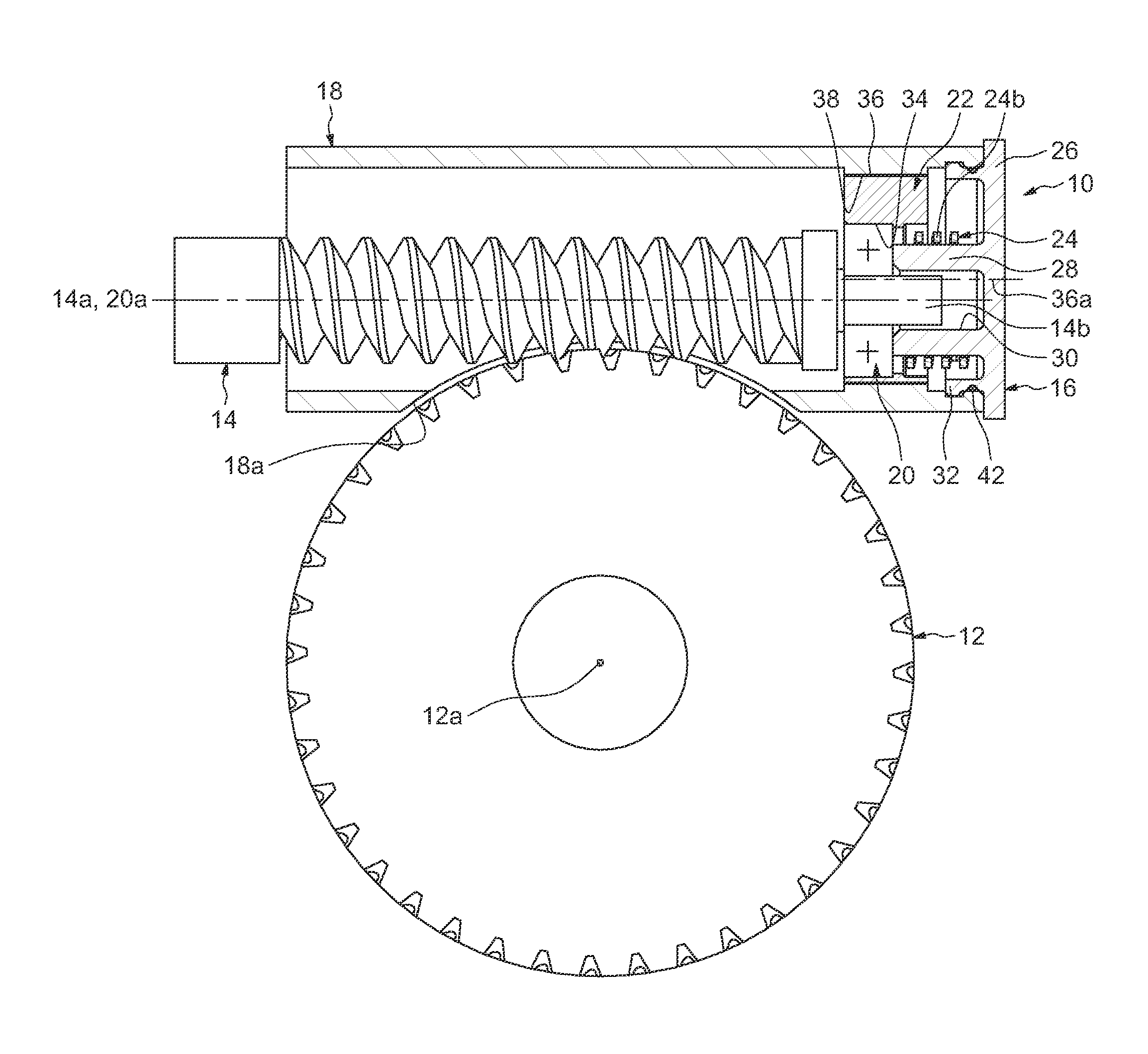
[0024]In FIG. 1, a wear-compensation device, referenced 10 in its entirety, is associated with a gear of the type with a wheel 12 and with a worm 14. The gear illustrated is a crossed gear set and the axes 12a, 14a of the toothed gear and of the worm are orthogonal.

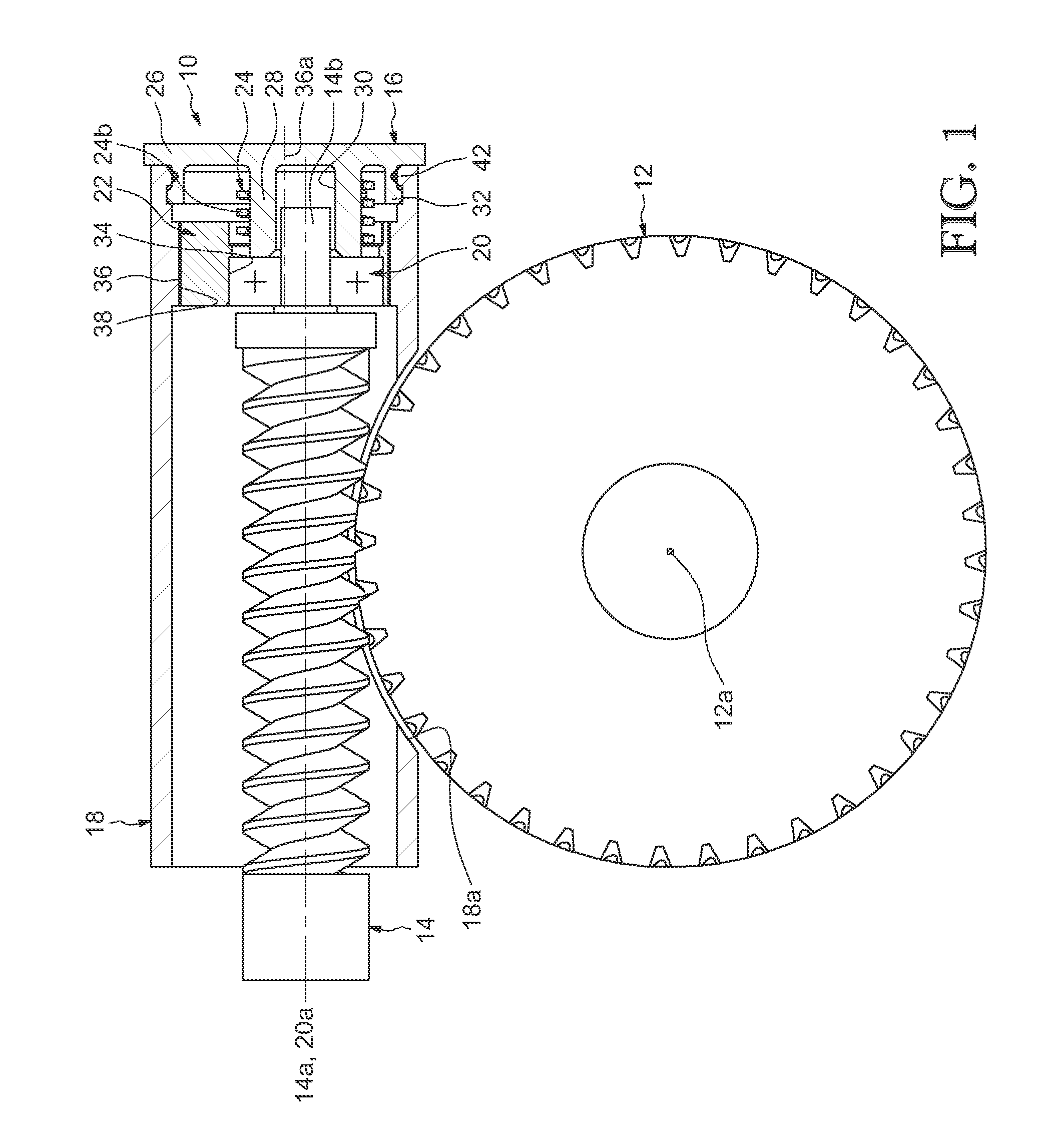
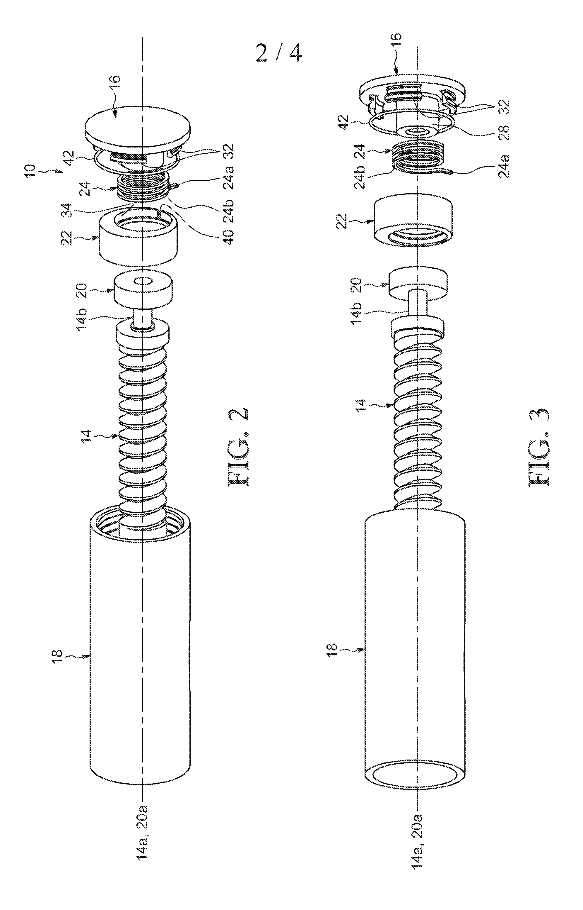
[0025]The device 10 comprises a fixed support 16 forming a cap designed to be mounted on a tubular housing 18 external to the said device, a rolling bearing 20 mounted on an end trunnion 14b of the worm, an eccentric 22 mounted on the rolling bearing, and a torsion spring 24 capable of applying a permanent circumferential force between the support 16 and the said eccentric. The worm 14 extends axially in the housing 18, the said housing comprising an opening 18a allowing the passage of the toothed wheel 12 so that the thread or threads of the worm mesh with the teeth of the wheel.

[0026]The bearing 20 (shown schematically) has a rotation axis 20a coaxial with the axis 14a of the worm. It comprises an inner ring mounted tig...


PUM


Abstract

The wear-compensation device for a gear comprises a fixed support capable of being fixed axially on an external element in order to keep the device on the said external element, a bearing designed to be mounted on a shaft comprising one of the wheels of the gear, an eccentric mounted on the bearing and designed to be in contact with the external element, the said eccentric being able to move angularly relative to the fixed support. The device also comprises a torsion spring mounted axially between the fixed support and the eccentric and capable of exerting a circumferential preload force on the said eccentric, the said spring comprising a first end mounted inside a recess of the eccentric and a second end interacting with the fixed support.

Description

CROSS-REFERENCE TO RELATED APPLICATION[0001]This U.S. Non-Provisional Utility application claims the benefit of co-pending French Patent Application Ser. No. 1151933, filed on Mar. 9, 2011, which is incorporated herein in its entirety.FIELD OF THE INVENTION[0002]The present invention relates to the field of wear-compensation devices for gear, notably used in assisted-steering mechanisms for motor vehicles.BACKGROUND OF THE INVENTION[0003]An assisted-steering mechanism usually comprises an electric assistance motor and a worm mounted on an output shaft of the said motor and meshing with a toothed wheel for example fixed to the shaft of the steering column or connected to the steering rack via an intermediate pinion.[0004]U.S. Pat. No. 6,763,738 B1 discloses an assisted-steering mechanism for a motor vehicle comprising means for adjusting the distance separating the axes of the worm and of the associated toothed wheel so as to be able to adjust the clearance that exists between the te...

Claims


Application Information

Patent Timeline
Patent Type & Authority Applications(United States)
IPC IPC(8): F16H57/023
CPCF16H1/16F16H2057/0224Y10T74/19619F16H55/24F16H57/022F16H2057/0213Y10T74/19828
Inventor LESCORAIL, ROMUALDGIRARDIN, CAROLEJANSEN, DANIEL
Owner AB SKF
Why Eureka
Try Eureka