
Rotating apparatus

Inactive Publication Date: 2012-09-13
CORETRONIC DISPLAY SOLUTION CORP
View PDF0 Cites 3 Cited by
  • Summary
  • Abstract
  • Description
  • Claims
  • Application Information

AI Technical Summary

Benefits of technology

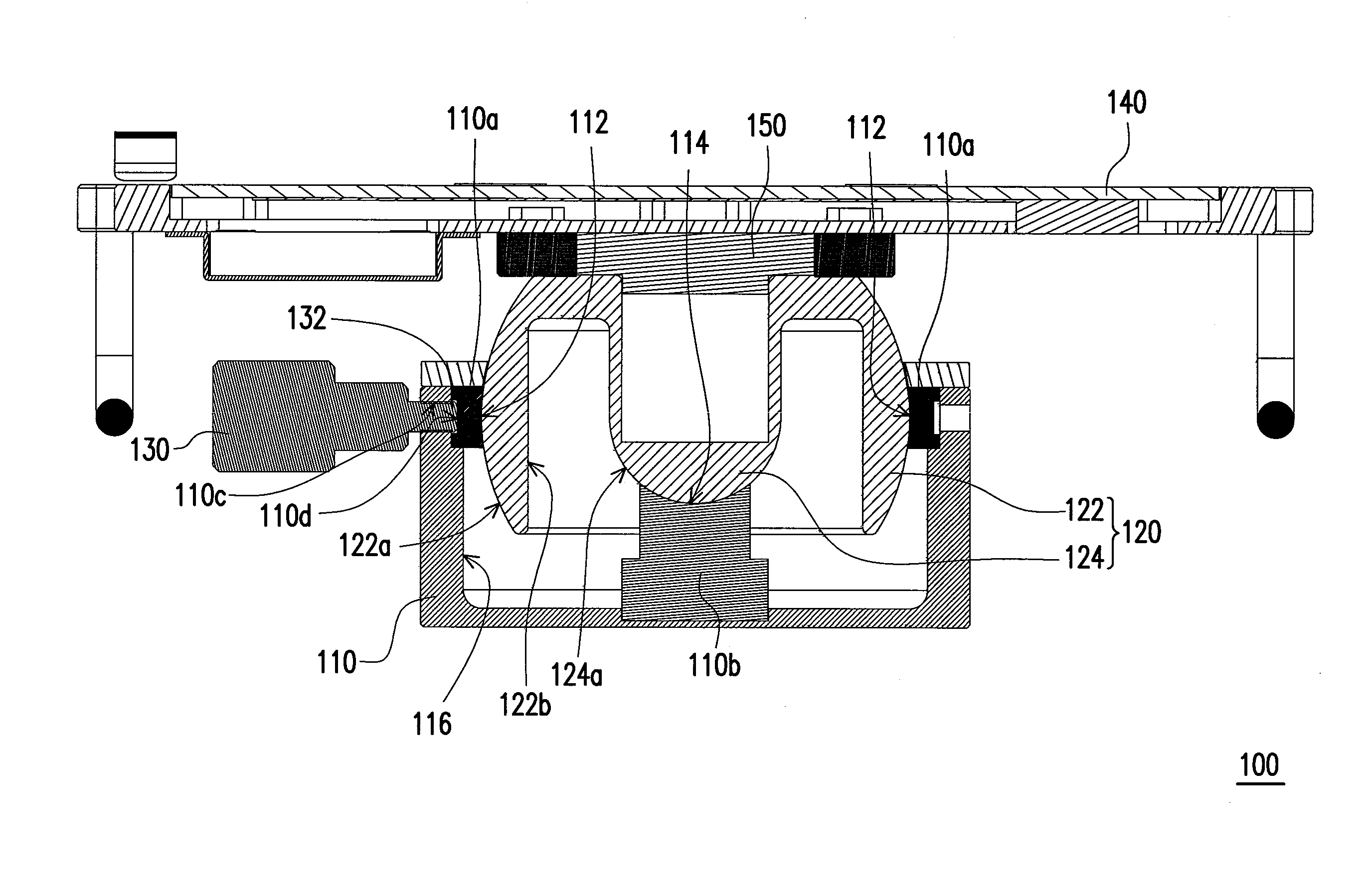
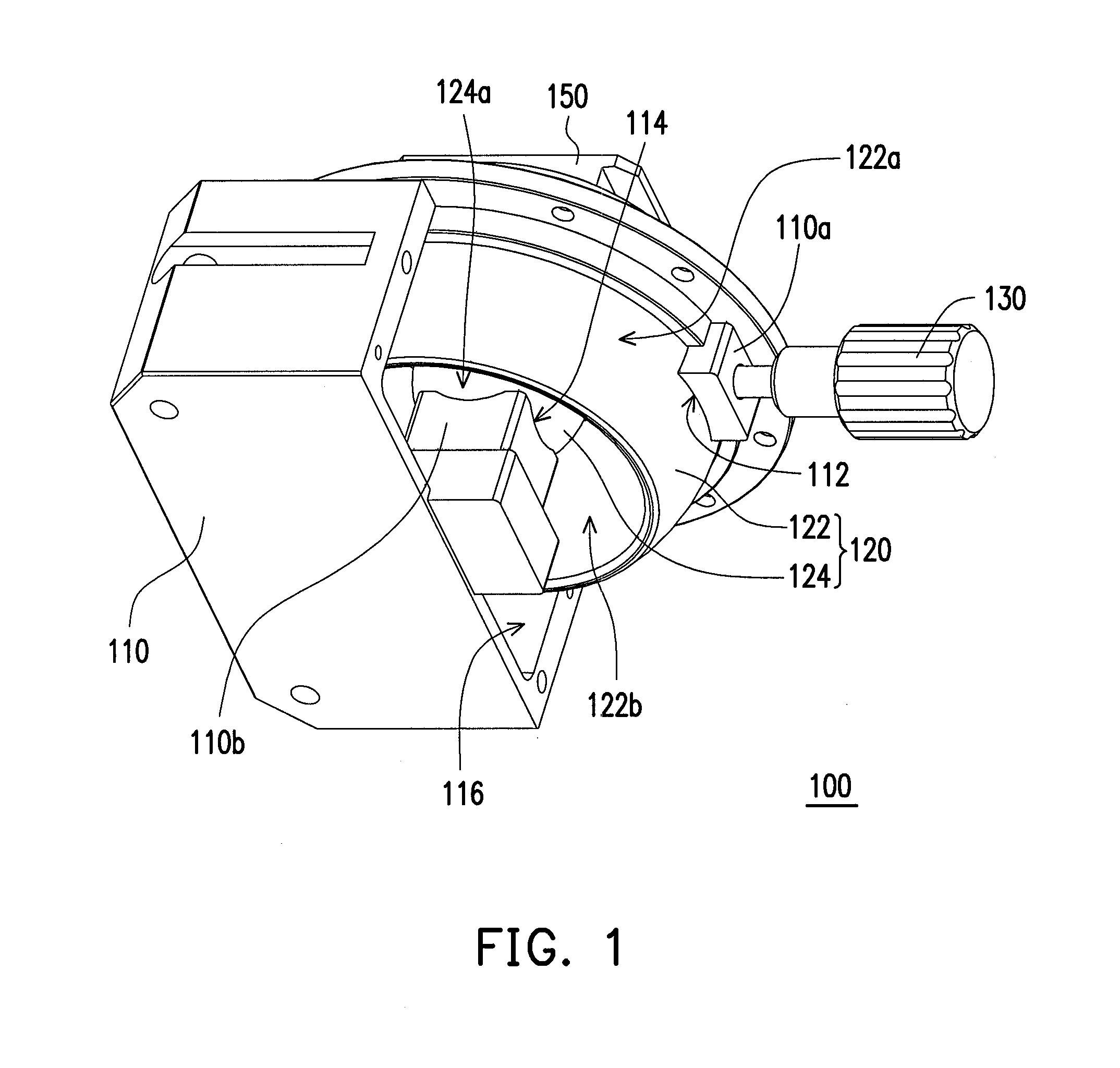
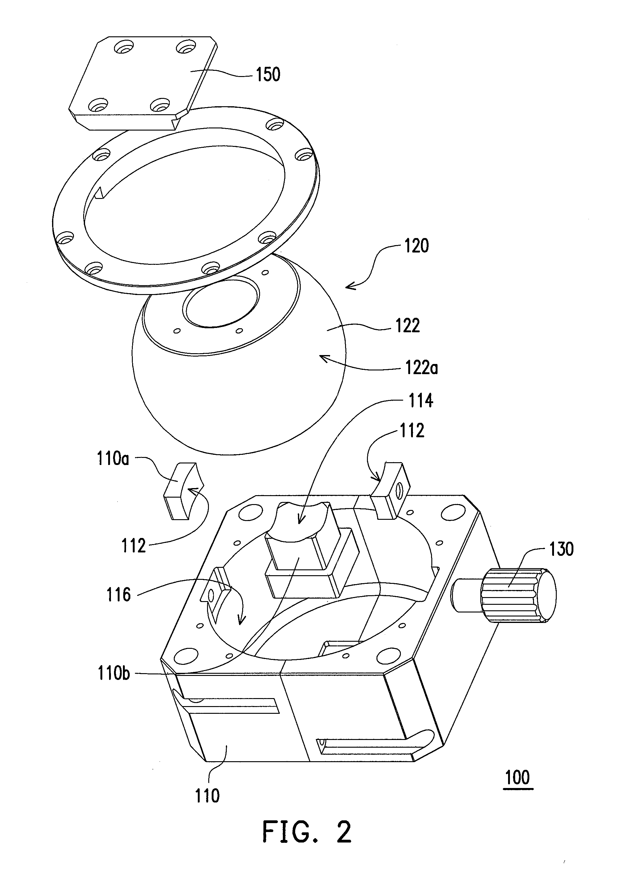
[0010]Based on the above, in the embodiment of the invention, besides the rotating element being universally jointed to the base through the first universally-jointing portion, it is further universally jointed to the base through the second universally-jointing portion fixed on the bottom of the first universally-jointing portion, wherein the curvature radius of the second convex spherical surface of the second universally-jointing portion is smaller than the curvature radius of the first convex spherical surface of the first universally-jointing portion, so the second universally-jointing portion has a smaller outer diameter. Since the rotating element is supported on the base by the second universally-jointing portion, thus the first universally-jointing portion with a bigger outer diameter does not need to provide a function for supporting the rotating element, and so the first convex spherical surface does not need to be designed to extend to the bottom of the first universally-jointing portion. As such, the height of the first universally-jointing portion may be reduced, further reducing the overall volume, thereby saving production cost and space.

Problems solved by technology

However, if the rotating apparatus has too great a volume, it will require a greater production cost and occupies a larger space.

Method used


Image

  • Rotating apparatus
  • Rotating apparatus
  • Rotating apparatus

Examples


Embodiment Construction

[0017]In the following detailed description of the preferred embodiments, reference is made to the accompanying drawings which form a part hereof, and in which are shown by way of illustration specific embodiments in which the invention may be practiced. In this regard, directional terminology, such as “top,”“bottom,”“front,”“back,” etc., is used with reference to the orientation of the Figure(s) being described. The components of the invention can be positioned in a number of different orientations. As such, the directional terminology is used for purposes of illustration and is in no way limiting. On the other hand, the drawings are only schematic and the sizes of components may be exaggerated for clarity. It is to be understood that other embodiments may be utilized and structural changes may be made without departing from the scope of the invention. Also, it is to be understood that the phraseology and terminology used herein are for the purpose of description and should not be ...


PUM


Abstract

A rotating apparatus including a base and a rotating element is provided. The base has first and second concave spherical surfaces. The rotating element includes first and second universally-jointing portions. The first universally-jointing portion has a first convex spherical surface. The first convex spherical surface is universally jointed to the first concave spherical surface. The second universally-jointing portion is fixed on the bottom of the first universally-jointing portion and has a second convex spherical surface. A curvature radius of the second convex spherical surface is smaller than a curvature radius of the first convex spherical surface. The first and second convex spherical surfaces have the same curvature center. The second convex spherical surface is universally jointed to the second concave spherical surface and the rotating element is supported on the second concave spherical surface of the base by the second universally-jointing portion.

Description

BACKGROUND OF THE INVENTION[0001]1. Field of the Invention[0002]The invention relates to a rotating apparatus and more particularly, to a rotating apparatus suitable to load a testing platform.[0003]2. Description of Related Art[0004]A medical ultrasound has advantages such as safety and low cost. Thus, medical ultrasounds are widely used during clinical diagnosis, for example, heart, abdomen, and maternity ultrasound check ups. In addition, the medical ultrasound may be further used for different medical experiments.[0005]For example, the medical ultrasound may be used on an experimental living body (i.e. mouse) for image scanning. The user may dispose the testing platform holding the mouse on a rotating apparatus, rotate the mouse body with the rotating apparatus, and proceed with ultrasound scanning on different parts of the mouse. In detail, the rotating apparatus may have a base with a spherical slot, and is assembled by universally-jointing with the spherical structure of the ...

Claims


Application Information

Patent Timeline
IPC IPC(8): A47B11/00F16D1/00
CPCF16M11/14Y10T403/32549Y10T403/32975F16M2200/022
Inventor TSENG, KUO-MING
Owner CORETRONIC DISPLAY SOLUTION CORP
Learn More