Cylinder Head for an Internal Combustion Engine, with Integrated Exhaust Manifold and Subgroups of Exhaust Conduits Merging into Manifold Portions which are Superimposed and Spaced Apart From Each Other

Active Publication Date: 2012-09-13
FIAT POWERTRAIN TECHNOLOGIES
View PDF6 Cites 23 Cited by
  • Summary
  • Abstract
  • Description
  • Claims
  • Application Information

AI Technical Summary

Benefits of technology

[0018]It should be observed that a cylinder head having the abovementioned characteristic (a) was previously proposed by the Applicant in the previous European patent application 10 425 161.6 thereof, still undisclosed as of date of priority of the present filing. The present invention makes reference to such previous proposal and combines it with the abovementioned further solutions, first of all providing subgroups of exhaust conduits merging into manifold portions superimposed and spaced apart from each other. The latter solution is per se known in the art (US 2010/0083920 A1, US 2009/0241526 A1) and allows advantages in terms of improved and more uniform cooling of the conduits also avoiding the gasdynamic interaction between the conduits, typical of the solutions with a single and neared outlet of the gas from the cylinde

Problems solved by technology

A drawback of the prior art solutions described above lies in the fact that the lower and upper cooling jackets are substantially traversed each by a longitudinal flow of a

Method used


Image

  • Cylinder Head for an Internal Combustion Engine, with Integrated Exhaust Manifold and Subgroups of Exhaust Conduits Merging into Manifold Portions which are Superimposed and Spaced Apart From Each Other
  • Cylinder Head for an Internal Combustion Engine, with Integrated Exhaust Manifold and Subgroups of Exhaust Conduits Merging into Manifold Portions which are Superimposed and Spaced Apart From Each Other
  • Cylinder Head for an Internal Combustion Engine, with Integrated Exhaust Manifold and Subgroups of Exhaust Conduits Merging into Manifold Portions which are Superimposed and Spaced Apart From Each Other

Examples


Embodiment Construction

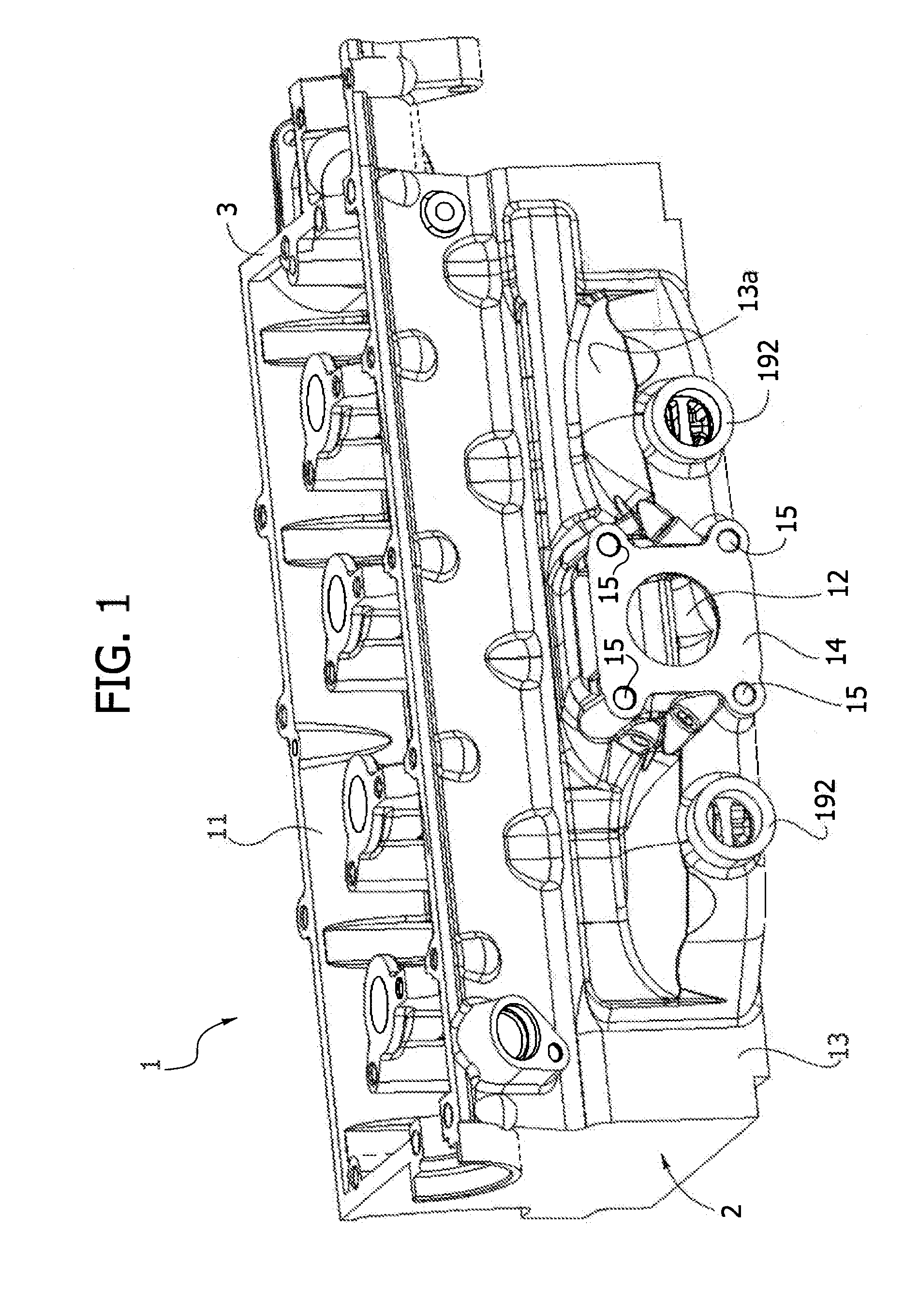
[0036]The illustrated example refers to the case of the cylinder head of a turbocharged internal combustion engine, with four in-line cylinders. It is however clear that the present invention may be applied to any other type of engine, with any number of cylinders and both in cases where a turbo-supercharger unit is provided for and in cases where such unit is not provided for.

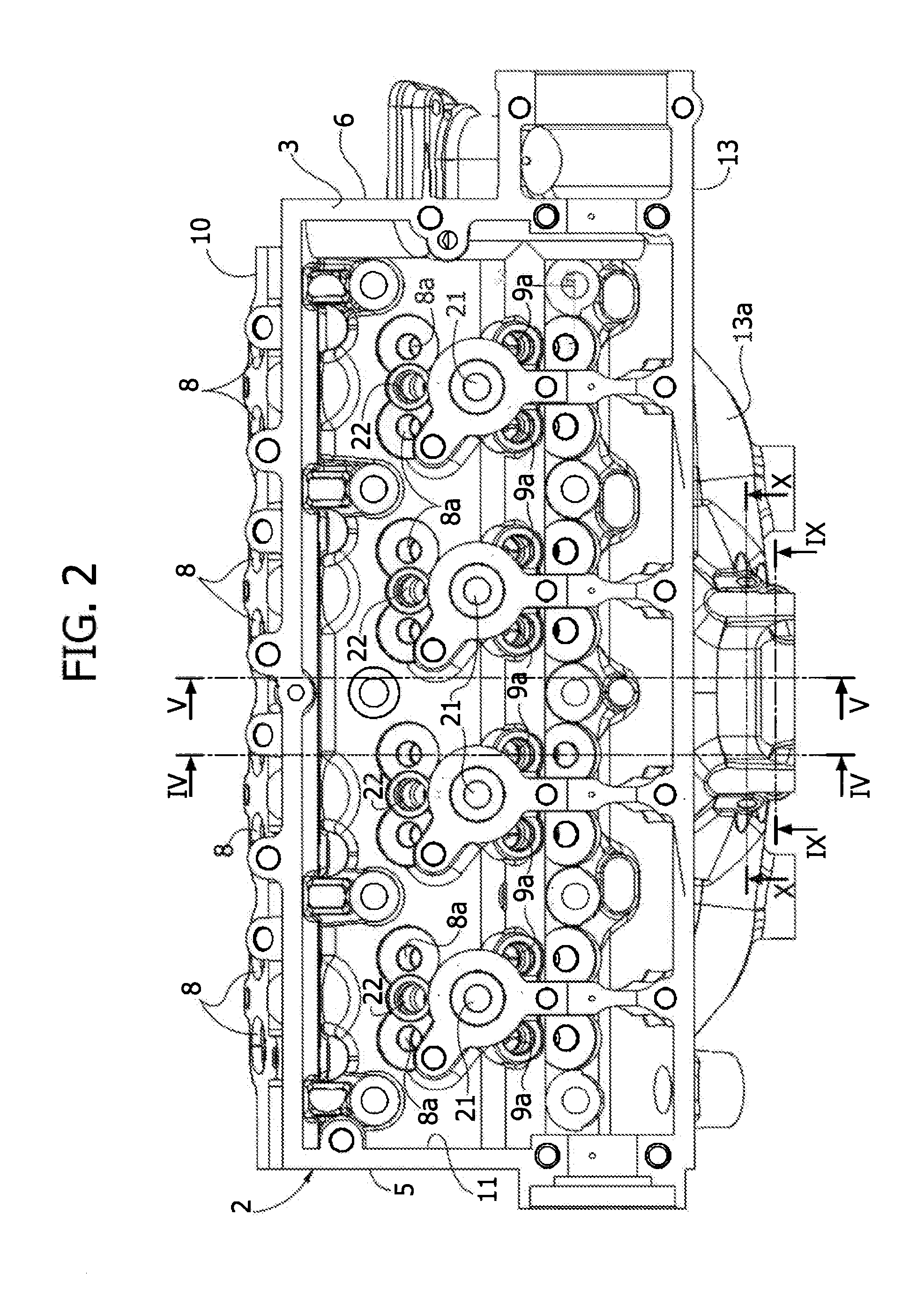
[0037]Referring to FIGS. 1-11, number 1 indicates—in its entirety—a cylinder head according to the invention, having a single aluminium body 2 with an upper face 3, a lower face 4 (see FIG. 3), a first end face 5 and a second end face 6.

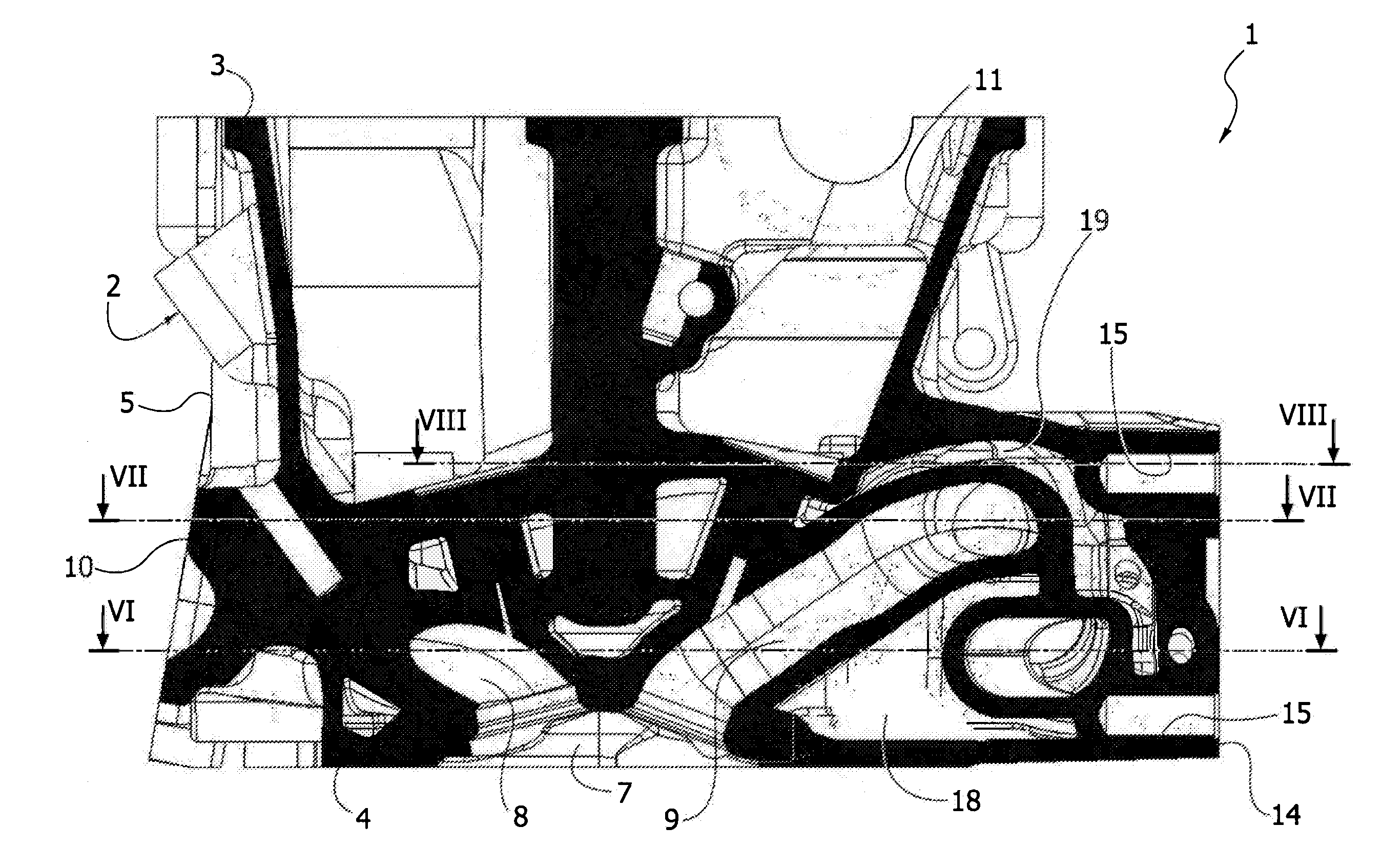
[0038]Cavities 7 (see FIGS. 4, 5) defining the combustion chambers associated to engine cylinders are formed in the lower face 4 of the cylinder head. The illustrated example refers to the case of an engine provided with two intake valves and two exhaust valves for each engine cylinder. Therefore, two intake conduits 8 and two exhaust conduits 9 (see FIGS. 4, 6) are formed by c...


PUM


Abstract

A cylinder head for an internal combustion engine has a body integrating, in a single cast piece, or exhaust manifold and including a lower cooling jacket and an upper cooling jacket. The lower cooling jacket is longitudinally divided into a plurality of separate transverse chambers associated to various engine cylinders, while the upper cooling jacket has a portion extending longitudinally over the entire development of the head and communicating with separate transverse chambers located on the intake side of the head. The exhaust conduits integrated in the head form separate subgroups of exhaust conduits merging into manifold portions superimposed and spaced apart from each other. The lower cooling jacket has a portion thereof which extends in the area of the body of the head which separates the superimposed portions of the abovementioned subgroups of exhaust conduits.

Description

FIELD OF THE INVENTION[0001]The present invention refers to cylinder heads for internal combustion engines of the type having:[0002]a body with an upper face, a lower face, two end faces and two lateral faces,[0003]said body integrating in a single cast piece, the engine exhaust manifold,[0004]said exhaust manifold being defined by a plurality of conduits for the exhaust gases provided in the body of the head, said conduits merging into a common outlet terminating on a lateral face of the head, and[0005]at least one lower cooling jacket and at least one upper cooling jacket provided in the body of the head, substantially below and above conduits defining the exhaust manifold.PRIOR ART[0006]Cylinder heads of the previously described type gave been known over the years. A cylinder head of this type, intended in particular for a turbocharged internal combustion engine, is described in document U.S. Pat. No. 4,993,227.[0007]The integration of the exhaust manifold in the cylinder head al...

Claims


Application Information

Patent Timeline
IPC IPC(8): F02F1/40
CPCF01N3/046F02F1/243F02F1/40F02F1/4264F01P2003/024F01N13/105Y02T10/20F01P3/02F01P3/14F01N13/10Y02T10/12
Inventor GALEAZZI, GIAMPAOLOABOZZI, ANTONIOD'ANNA, CARMELO
Owner FIAT POWERTRAIN TECHNOLOGIES
Why Eureka
Try Eureka